ATmega640/1280/1281/2560/2561
Low Frequency Crystal
Oscillator
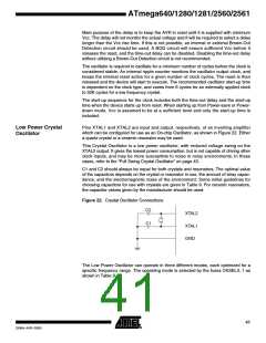
The device can utilize a 32.768 kHz watch crystal as clock source by a dedicated Low
Frequency Crystal Oscillator. The crystal should be connected as shown in Figure 22.
When this Oscillator is selected, start-up times are determined by the SUT Fuses and
CKSEL0 as shown in Table 13.
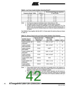
Table 13. Start-up Times for the Low Frequency Crystal Oscillator Clock Selection
Start-up Time from
Power-down and
Power-save
Additional Delay
from Reset
Power Conditions
BOD enabled
(VCC = 5.0V)
CKSEL0 SUT1..0
1K CK
1K CK
14CK(1)
0
0
0
0
1
1
1
1
00
01
10
11
00
01
10
11
Fast rising power
Slowly rising power
14CK + 4.1 ms(1)
14CK + 65 ms(1)
1K CK
Reserved
32K CK
32K CK
32K CK
Reserved
BOD enabled
14CK
Fast rising power
Slowly rising power
14CK + 4.1 ms
14CK + 65 ms
Note:
1. These options should only be used if frequency stability at start-up is not important
for the application.
Calibrated Internal RC
Oscillator
The calibrated internal RC Oscillator by default provides a 8.0 MHz clock. The frequency
is nominal value at 3V and 25°C. The device is shipped with the CKDIV8 Fuse pro-
grammed. See “System Clock Prescaler” on page 48 for more details. This clock may
be selected as the system clock by programming the CKSEL Fuses as shown in Table
14. If selected, it will operate with no external components. During reset, hardware loads
the calibration byte into the OSCCAL Register and thereby automatically calibrates the
RC Oscillator. At 3V and 25°C, this calibration gives a frequency of 8 MHz 1ꢀ. The
oscillator can be calibrated to any frequency in the range 7.3 - 8.1 MHz within 1ꢀ
accuracy, by changing the OSCCAL register. When this Oscillator is used as the chip
clock, the Watchdog Oscillator will still be used for the Watchdog Timer and for the
Reset Time-out. For more information on the pre-programmed calibration value, see the
section “Calibration Byte” on page 338.
Table 14. Internal Calibrated RC Oscillator Operating Modes(1)(3)
Frequency Range(2) (MHz)
CKSEL3..0
7.3 - 8.1
0010
Notes: 1. The device is shipped with this option selected.
2. The frequency ranges are preliminary values. Actual values are TBD.
3. If 8 MHz frequency exceeds the specification of the device (depends on VCC), the
CKDIV8 Fuse can be programmed in order to divide the internal frequency by 8.
When this Oscillator is selected, start-up times are determined by the SUT Fuses as
shown in Table 15 on page 46.
45
2549A–AVR–03/05

 ATMEL [ ATMEL ]