ATmega640/1280/1281/2560/2561
8-bit Timer/Counter2 Timer/Counter2 is a general purpose, single channel, 8-bit Timer/Counter module. The
main features are:
• Single Channel Counter
• Clear Timer on Compare Match (Auto Reload)
• Glitch-free, Phase Correct Pulse Width Modulator (PWM)
with PWM and
Asynchronous
Operation
• Frequency Generator
• 10-bit Clock Prescaler
• Overflow and Compare Match Interrupt Sources (TOV2, OCF2A and OCF2B)
• Allows Clocking from External 32 kHz Watch Crystal Independent of the I/O Clock
Overview
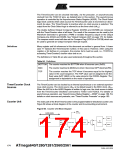
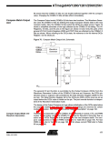
A simplified block diagram of the 8-bit Timer/Counter is shown in Figure 60.. For the
actual placement of I/O pins, see “Pin Configurations” on page 2. CPU accessible I/O
Registers, including I/O bits and I/O pins, are shown in bold. The device-specific I/O
Register and bit locations are listed in the “8-bit Timer/Counter Register Description” on
page 184.
The Power Reduction Timer/Counter2 bit, PRTIM2, in “Power Reduction Register 0 -
PRR0” on page 54 must be written to zero to enable Timer/Counter2 module.
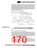
Figure 67. 8-bit Timer/Counter Block Diagram
Count
TOVn
(Int.Req.)
Clear
Control Logic
Direction
clkTn
TOSC1
TOSC2
T/C
Oscillator
Prescaler
TOP
BOTTOM
clkI/O
Timer/Counter
TCNTn
=
= 0
OCnA
(Int.Req.)
Waveform
Generation
OCnA
OCnB
=
OCRnA
Fixed
TOP
Value
OCnB
(Int.Req.)
Waveform
Generation
=
OCRnB
clkI/O
Synchronized Status flags
Synchronization Unit
clkASY
asynchronous mode
select (ASn)
Status flags
ASSRn
TCCRnA
TCCRnB
Registers
The Timer/Counter (TCNT2) and Output Compare Register (OCR2A and OCR2B) are
8-bit registers. Interrupt request (abbreviated to Int.Req.) signals are all visible in the
Timer Interrupt Flag Register (TIFR2). All interrupts are individually masked with the
Timer Interrupt Mask Register (TIMSK2). TIFR2 and TIMSK2 are not shown in the
figure.
173
2549A–AVR–03/05

 ATMEL [ ATMEL ]