22.3 Mode of Operation
22.3.1
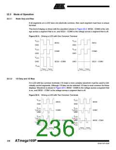
Static Duty and Bias
If all segments on a LCD have one electrode common, then each segment must have a unique
terminal.
This kind of display is driven with the waveform shown in Figure 22-3. SEG0 - COM0 is the volt-
age across a segment that is on, and SEG1 - COM0 is the voltage across a segment that is off.
Figure 22-3. Driving a LCD with One Common Terminal
V
V
LCD
LCD
SEG0
COM0
SEG1
COM0
GND
GND
V
V
LCD
LCD
GND
GND
V
LCD
GND
SEG0 - COM0
GND
SEG1 - COM0
-V
LCD
Frame
Frame
Frame
Frame
22.3.2
1/2 Duty and 1/2 Bias
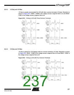
For LCD with two common terminals (1/2 duty) a more complex waveform must be used to indi-
vidually control segments. Although 1/3 bias can be selected 1/2 bias is most common for these
displays. Waveform is shown in Figure 22-4. SEG0 - COM0 is the voltage across a segment that
is on, and SEG0 - COM1 is the voltage across a segment that is off.
Figure 22-4. Driving a LCD with Two Common Terminals
V
V
LCD
LCD
SEG0
COM0
SEG0
COM1
GND
GND
V
V
LCD
LCD
1
1
/ V
/ V
2
LCD
2 LCD
GND
GND
V
V
LCD
LCD
1
1
/ V
/ V
2
LCD
2 LCD
GND
SEG0 - COM0
GND
SEG0 - COM1
-1
-1
/ V
/ V
2
LCD
LCD
2
LCD
LCD
-V
-V
Frame
Frame
Frame
Frame
236
ATmega169P
8018A–AVR–03/06

 ATMEL [ ATMEL ]