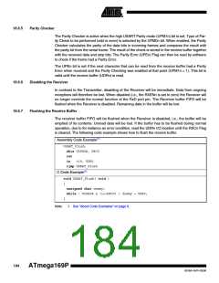
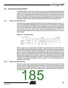
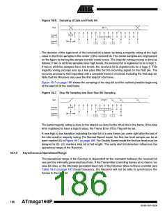
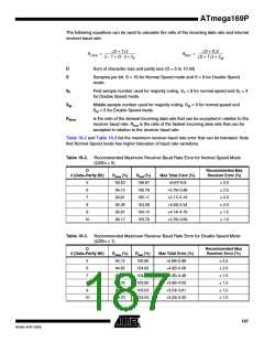
The recommendations of the maximum receiver baud rate error was made under the assump-
tion that the Receiver and Transmitter equally divides the maximum total error.
There are two possible sources for the receivers baud rate error. The Receiver’s system clock
(XTAL) will always have some minor instability over the supply voltage range and the tempera-
ture range. When using a crystal to generate the system clock, this is rarely a problem, but for a
resonator the system clock may differ more than 2ꢀ depending of the resonators tolerance. The
second source for the error is more controllable. The baud rate generator can not always do an
exact division of the system frequency to get the baud rate wanted. In this case an UBRRn value
that gives an acceptable low error can be used if possible.
18.8 Multi-processor Communication Mode
Setting the Multi-processor Communication mode (MPCMn) bit in UCSRnA enables a filtering
function of incoming frames received by the USART Receiver. Frames that do not contain
address information will be ignored and not put into the receive buffer. This effectively reduces
the number of incoming frames that has to be handled by the CPU, in a system with multiple
MCUs that communicate via the same serial bus. The Transmitter is unaffected by the MPCMn
setting, but has to be used differently when it is a part of a system utilizing the Multi-processor
Communication mode.
If the Receiver is set up to receive frames that contain 5 to 8 data bits, then the first stop bit indi-
cates if the frame contains data or address information. If the Receiver is set up for frames with
nine data bits, then the ninth bit (RXB8n) is used for identifying address and data frames. When
the frame type bit (the first stop or the ninth bit) is one, the frame contains an address. When the
frame type bit is zero the frame is a data frame.
The Multi-processor Communication mode enables several slave MCUs to receive data from a
master MCU. This is done by first decoding an address frame to find out which MCU has been
addressed. If a particular slave MCU has been addressed, it will receive the following data
frames as normal, while the other slave MCUs will ignore the received frames until another
address frame is received.
18.8.1
Using MPCMn
For an MCU to act as a master MCU, it can use a 9-bit character frame format (UCSZ = 7). The
ninth bit (TXB8n) must be set when an address frame (TXB8n = 1) or cleared when a data frame
(TXB = 0) is being transmitted. The slave MCUs must in this case be set to use a 9-bit character
frame format.
The following procedure should be used to exchange data in Multi-processor Communication
mode:
1. All Slave MCUs are in Multi-processor Communication mode (MPCMn in UCSRnA is
set).
2. The Master MCU sends an address frame, and all slaves receive and read this frame. In
the Slave MCUs, the RXCn Flag in UCSRnA will be set as normal.
3. Each Slave MCU reads the UDRn Register and determines if it has been selected. If so,
it clears the MPCMn bit in UCSRnA, otherwise it waits for the next address byte and
keeps the MPCMn setting.
4. The addressed MCU will receive all data frames until a new address frame is received.
The other Slave MCUs, which still have the MPCMn bit set, will ignore the data frames.
188
ATmega169P
8018A–AVR–03/06

 ATMEL [ ATMEL ]