ATmega169P
UDREn is set after a reset to indicate that the Transmitter is ready.
• Bit 4 – FEn: Frame Error n
This bit is set if the next character in the receive buffer had a Frame Error when received. I.e.,
when the first stop bit of the next character in the receive buffer is zero. This bit is valid until the
receive buffer (UDRn) is read. The FEn bit is zero when the stop bit of received data is one.
Always set this bit to zero when writing to UCSRnA.
• Bit 3 – DORn: Data OverRun n
This bit is set if a Data OverRun condition is detected. A Data OverRun occurs when the receive
buffer is full (two characters), it is a new character waiting in the Receive Shift Register, and a
new start bit is detected. This bit is valid until the receive buffer (UDRn) is read. Always set this
bit to zero when writing to UCSRnA.
• Bit 2 – UPEn: USART Parity Error n
This bit is set if the next character in the receive buffer had a Parity Error when received and the
Parity Checking was enabled at that point (UPM1n = 1). This bit is valid until the receive buffer
(UDRn) is read. Always set this bit to zero when writing to UCSRnA.
• Bit 1 – U2Xn: Double the USART Transmission Speed n
This bit only has effect for the asynchronous operation. Write this bit to zero when using syn-
chronous operation.
Writing this bit to one will reduce the divisor of the baud rate divider from 16 to 8 effectively dou-
bling the transfer rate for asynchronous communication.
• Bit 0 – MPCMn: Multi-processor Communication Mode n
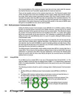
This bit enables the Multi-processor Communication mode. When the MPCMn bit is written to
one, all the incoming frames received by the USART Receiver that do not contain address infor-
mation will be ignored. The Transmitter is unaffected by the MPCMn setting. For more detailed
information see ”Multi-processor Communication Mode” on page 188.
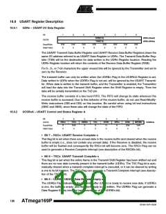
18.9.3
UCSRnB – USART Control and Status Register n B
Bit
(0xC1)
7
6
5
4
RXENn
R/W
0
3
TXENn
R/W
0
2
UCSZn2
R/W
1
0
TXB8n
R/W
0
RXCIEn
TXCIEn
UDRIEn
RXB8n
UCSRBn
Read/Write
Initial Value
R/W
0
R/W
0
R/W
0
R
0
0
• Bit 7 – RXCIEn: RX Complete Interrupt Enable n
Writing this bit to one enables interrupt on the RXC Flag. A USART Receive Complete interrupt
will be generated only if the RXCIE bit is written to one, the Global Interrupt Flag in SREG is writ-
ten to one and the RXC bit in UCSRnA is set.
• Bit 6 – TXCIEn: TX Complete Interrupt Enable n
Writing this bit to one enables interrupt on the TXCn Flag. A USART Transmit Complete interrupt
will be generated only if the TXCIEn bit is written to one, the Global Interrupt Flag in SREG is
written to one and the TXCn bit in UCSRnA is set.
191
8018A–AVR–03/06

 ATMEL [ ATMEL ]