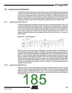
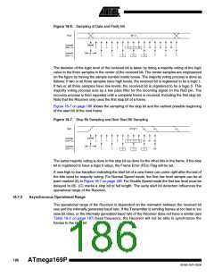
Figure 18-6. Sampling of Data and Parity Bit
RxD
BIT n
Sample
(U2X = 0)
1
1
2
3
2
4
5
3
6
7
4
8
9
5
10
11
6
12
13
7
14
15
8
16
1
1
Sample
(U2X = 1)
The decision of the logic level of the received bit is taken by doing a majority voting of the logic
value to the three samples in the center of the received bit. The center samples are emphasized
on the figure by having the sample number inside boxes. The majority voting process is done as
follows: If two or all three samples have high levels, the received bit is registered to be a logic 1.
If two or all three samples have low levels, the received bit is registered to be a logic 0. This
majority voting process acts as a low pass filter for the incoming signal on the RxD pin. The
recovery process is then repeated until a complete frame is received. Including the first stop bit.
Note that the Receiver only uses the first stop bit of a frame.
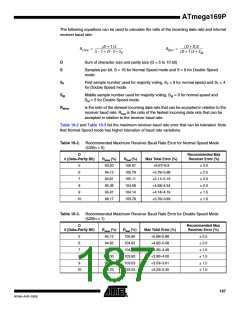
Figure 18-7 on page 186 shows the sampling of the stop bit and the earliest possible beginning
of the start bit of the next frame.
Figure 18-7. Stop Bit Sampling and Next Start Bit Sampling
(A)
(B)
(C)
RxD
STOP 1
Sample
(U2X = 0)
1
1
2
3
2
4
5
3
6
7
4
8
9
5
10
0/1 0/1 0/1
Sample
(U2X = 1)
6
0/1
The same majority voting is done to the stop bit as done for the other bits in the frame. If the stop
bit is registered to have a logic 0 value, the Frame Error (FEn) Flag will be set.
A new high to low transition indicating the start bit of a new frame can come right after the last of
the bits used for majority voting. For Normal Speed mode, the first low level sample can be at
point marked (A) in Figure 18-7 on page 186. For Double Speed mode the first low level must be
delayed to (B). (C) marks a stop bit of full length. The early start bit detection influences the
operational range of the Receiver.
18.7.3
Asynchronous Operational Range
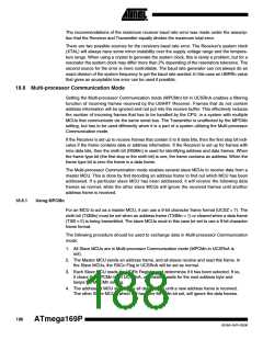
The operational range of the Receiver is dependent on the mismatch between the received bit
rate and the internally generated baud rate. If the Transmitter is sending frames at too fast or too
slow bit rates, or the internally generated baud rate of the Receiver does not have a similar (see
Table 18-2 on page 187) base frequency, the Receiver will not be able to synchronize the
frames to the start bit.
186
ATmega169P
8018A–AVR–03/06

 ATMEL [ ATMEL ]