• Bit 5 – UDRIEn: USART Data Register Empty Interrupt Enable
Writing this bit to one enables interrupt on the UDREn Flag. A Data Register Empty interrupt will
be generated only if the UDRIEn bit is written to one, the Global Interrupt Flag in SREG is written
to one and the UDREn bit in UCSRnA is set.
• Bit 4 – RXENn: Receiver Enable n
Writing this bit to one enables the USART Receiver. The Receiver will override normal port oper-
ation for the RxD pin when enabled. Disabling the Receiver will flush the receive buffer
invalidating the FEn, DORn, and UPEn Flags.
• Bit 3 – TXENn: Transmitter Enable n
Writing this bit to one enables the USART Transmitter. The Transmitter will override normal port
operation for the TxD pin when enabled. The disabling of the Transmitter (writing TXENn to
zero) will not become effective until ongoing and pending transmissions are completed, i.e.,
when the Transmit Shift Register and Transmit Buffer Register do not contain data to be trans-
mitted. When disabled, the Transmitter will no longer override the TxD port.
• Bit 2 – UCSZn2: Character Size n
The UCSZn2 bits combined with the UCSZ1n:0 bit in UCSRnC sets the number of data bits
(Character SiZe) in a frame the Receiver and Transmitter use.
• Bit 1 – RXB8n: Receive Data Bit 8 n
RXB8n is the ninth data bit of the received character when operating with serial frames with nine
data bits. Must be read before reading the low bits from UDRn.
• Bit 0 – TXB8n: Transmit Data Bit 8 n
TXB8n is the ninth data bit in the character to be transmitted when operating with serial frames
with nine data bits. Must be written before writing the low bits to UDRn.
18.9.4
UCSRnC – USART Control and Status Register n C
Bit
(0xC2)
7
6
5
4
UPM0n
R/W
0
3
USBSn
R/W
0
2
UCSZn1
R/W
1
UCSZn0
R/W
0
UCPOLn
R/W
–
UMSELn
UPM1n
UCSRnC
Read/Write
Initial Value
R
0
R/W
0
R/W
0
1
1
0
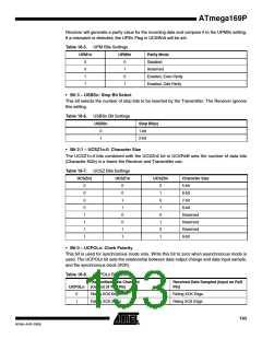
• Bit 6 – UMSELn: USART Mode Select n
This bit selects between asynchronous and synchronous mode of operation.
Table 18-4. UMSELn Bit Settings
UMSELn
Mode
0
1
Asynchronous Operation
Synchronous Operation
• Bit 5:4 – UPM1n:0: Parity Mode
These bits enable and set type of parity generation and check. If enabled, the Transmitter will
automatically generate and send the parity of the transmitted data bits within each frame. The
192
ATmega169P
8018A–AVR–03/06

 ATMEL [ ATMEL ]