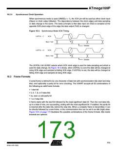
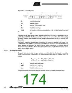
Figure 18-4. Frame Formats
FRAME
[5]
(IDLE)
St
0
1
2
3
4
[6]
[7]
[8]
[P] Sp1 [Sp2] (St / IDLE)
St
Start bit, always low.
Data bits (0 to 8).
(n)
P
Parity bit. Can be odd or even.
Stop bit, always high.
Sp
IDLE
No transfers on the communication line (RxD or TxD). An IDLE line must
high.
be
The frame format used by the USART is set by the UCSZn2:0, UPM1n:0 and USBSn bits in
UCSRnB and UCSRnC. The Receiver and Transmitter use the same setting. Note that changing
the setting of any of these bits will corrupt all ongoing communication for both the Receiver and
Transmitter.
The USART Character SiZe (UCSZn2:0) bits select the number of data bits in the frame. The
USART Parity mode (UPM1n:0) bits enable and set the type of parity bit. The selection between
one or two stop bits is done by the USART Stop Bit Select (USBSn) bit. The Receiver ignores
the second stop bit. An FEn (Frame Error FEn) will therefore only be detected in the cases
where the first stop bit is zero.
18.3.1
Parity Bit Calculation
The parity bit is calculated by doing an exclusive-or of all the data bits. If odd parity is used, the
result of the exclusive or is inverted. The relation between the parity bit and data bits is as
follows:
P
P
= d
= d
⊕ … ⊕ d ⊕ d ⊕ d ⊕ d ⊕ 0
3 2 1 0
even
n – 1
n – 1
⊕ … ⊕ d ⊕ d ⊕ d ⊕ d ⊕ 1
odd
3 2 1 0
Peven
Podd
dn
Parity bit using even parity
Parity bit using odd parity
Data bit n of the character
If used, the parity bit is located between the last data bit and first stop bit of a serial frame.
174
ATmega169P
8018A–AVR–03/06

 ATMEL [ ATMEL ]