The PWM frequency for the output can be calculated by the following equation:
f
clk_I/O
f
= -----------------
OCnPWM
N ⋅ 256
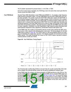
The N variable represents the prescale factor (1, 8, 64, 256, or 1024).
The extreme values for the OCR2 Register represents special cases when generating a PWM
waveform output in the fast PWM mode. If the OCR2 is set equal to BOTTOM, the output will be
a narrow spike for each MAX+1 timer clock cycle. Setting the OCR2 equal to MAX will result in a
constantly high or low output (depending on the polarity of the output set by the COM21:0 bits.)
A frequency (with 50% duty cycle) waveform output in fast PWM mode can be achieved by set-
ting OC2 to toggle its logical level on each compare match (COM21:0 = 1). The waveform
generated will have a maximum frequency of fOC2 = fclk_I/O/2 when OCR2 is set to zero. This fea-
ture is similar to the OC2 toggle in CTC mode, except the double buffer feature of the output
compare unit is enabled in the fast PWM mode.
152
ATmega128(L)
2467P–AVR–08/07

 ATMEL [ ATMEL ]