ATmega128(L)
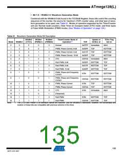
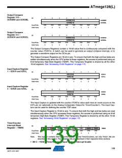
• Bit 1:0 – WGMn1:0: Waveform Generation Mode
Combined with the WGMn3:2 bits found in the TCCRnB Register, these bits control the counting
sequence of the counter, the source for maximum (TOP) counter value, and what type of wave-
form generation to be used, see Table 61. Modes of operation supported by the Timer/Counter
unit are: Normal mode (counter), Clear Timer on Compare match (CTC) mode, and three types
of Pulse Width Modulation (PWM) modes. (See “Modes of Operation” on page 124.)
Table 61. Waveform Generation Mode Bit Description
WGMn2
(CTCn)
WGMn1
(PWMn1) (PWMn0)
WGMn0
Timer/Counter Mode of
Operation(1)
Update of
OCRnx at
TOVn Flag
Set on
Mode WGMn3
TOP
0
1
2
3
4
5
6
7
8
0
0
0
0
0
0
0
0
1
0
0
0
0
1
1
1
1
0
0
0
1
1
0
0
1
1
0
0
1
0
1
0
1
0
1
0
Normal
0xFFFF Immediate
MAX
PWM, Phase Correct, 8-bit
PWM, Phase Correct, 9-bit
PWM, Phase Correct, 10-bit
CTC
0x00FF
0x01FF
0x03FF
OCRnA
0x00FF
0x01FF
0x03FF
TOP
BOTTOM
BOTTOM
BOTTOM
MAX
TOP
TOP
Immediate
BOTTOM
BOTTOM
BOTTOM
Fast PWM, 8-bit
TOP
Fast PWM, 9-bit
TOP
Fast PWM, 10-bit
TOP
PWM, Phase and Frequency
Correct
ICRn
BOTTOM
BOTTOM
BOTTOM
BOTTOM
9
1
0
0
1
PWM, Phase and Frequency
Correct
OCRnA
10
11
12
13
14
1
1
1
1
1
1
0
0
1
1
1
1
1
1
0
0
1
1
0
1
0
1
0
1
PWM, Phase Correct
PWM, Phase Correct
CTC
ICRn
OCRnA
ICRn
–
TOP
BOTTOM
BOTTOM
MAX
TOP
Immediate
–
(Reserved)
–
Fast PWM
ICRn
OCRnA
BOTTOM
BOTTOM
TOP
15
Fast PWM
TOP
Note:
1. The CTCn and PWMn1:0 bit definition names are obsolete. Use the WGMn2:0 definitions. However, the functionality and
location of these bits are compatible with previous versions of the timer.
135
2467P–AVR–08/07

 ATMEL [ ATMEL ]