ATmega640/1280/1281/2560/2561
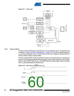
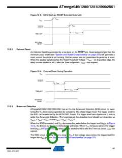
Figure 12-3. MCU Start-up, RESET Extended Externally
VPOT
VCC
VRST
RESET
tTOUT
TIME-OUT
INTERNAL
RESET
12.2.2
External Reset
An External Reset is generated by a low level on the RESET pin. Reset pulses longer than the
minimum pulse width (see “System and Reset Characteristics” on page 375) will generate a
reset, even if the clock is not running. Shorter pulses are not guaranteed to generate a reset.
When the applied signal reaches the Reset Threshold Voltage – VRST – on its positive edge, the
delay counter starts the MCU after the Time-out period – tTOUT – has expired.
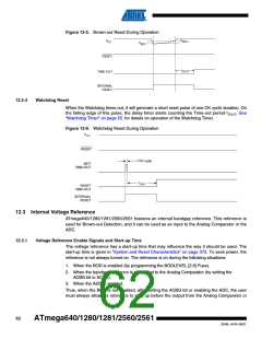
Figure 12-4. External Reset During Operation
CC
12.2.3
Brown-out Detection
ATmega640/1280/1281/2560/2561 has an On-chip Brown-out Detection (BOD) circuit for moni-
toring the VCC level during operation by comparing it to a fixed trigger level. The trigger level for
the BOD can be selected by the BODLEVEL Fuses. The trigger level has a hysteresis to ensure
spike free Brown-out Detection. The hysteresis on the detection level should be interpreted as
V
BOT+ = VBOT + VHYST/2 and VBOT- = VBOT - VHYST/2.
When the BOD is enabled, and VCC decreases to a value below the trigger level (VBOT- in Figure
12-5), the Brown-out Reset is immediately activated. When VCC increases above the trigger
level (VBOT+ in Figure 12-5), the delay counter starts the MCU after the Time-out period tTOUT has
expired.
The BOD circuit will only detect a drop in VCC if the voltage stays below the trigger level for
longer than tBOD given in “System and Reset Characteristics” on page 375.
61
2549L–AVR–08/07

 ATMEL [ ATMEL ]