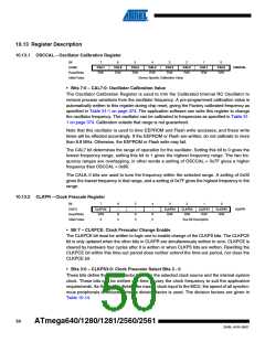
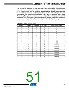
stopped during sleep. If the Timer/Counter2 is not using the synchronous clock, the clock source
is stopped during sleep. Note that even if the synchronous clock is running in Power-save, this
clock is only available for the Timer/Counter2.
11.6 Standby Mode
When the SM2:0 bits are 110 and an external crystal/resonator clock option is selected, the
SLEEP instruction makes the MCU enter Standby mode. This mode is identical to Power-down
with the exception that the Oscillator is kept running. From Standby mode, the device wakes up
in six clock cycles.
11.7 Extended Standby Mode
When the SM2:0 bits are 111 and an external crystal/resonator clock option is selected, the
SLEEP instruction makes the MCU enter Extended Standby mode. This mode is identical to
Power-save mode with the exception that the Oscillator is kept running. From Extended Standby
mode, the device wakes up in six clock cycles.Power Reduction Register
The Power Reduction Register (PRR), see “PRR0 – Power Reduction Register 0” on page 56
and “PRR1 – Power Reduction Register 1” on page 57, provides a method to stop the clock to
individual peripherals to reduce power consumption. The current state of the peripheral is frozen
and the I/O registers can not be read or written. Resources used by the peripheral when stop-
ping the clock will remain occupied, hence the peripheral should in most cases be disabled
before stopping the clock. Waking up a module, which is done by clearing the bit in PRR, puts
the module in the same state as before shutdown.
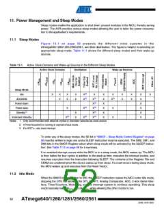
Module shutdown can be used in Idle mode and Active mode to significantly reduce the overall
power consumption. See “Supply Current of IO modules” on page 392 for examples. In all other
sleep modes, the clock is already stopped.
11.8 Minimizing Power Consumption
There are several issues to consider when trying to minimize the power consumption in an AVR
controlled system. In general, sleep modes should be used as much as possible, and the sleep
mode should be selected so that as few as possible of the device’s functions are operating. All
functions not needed should be disabled. In particular, the following modules may need special
consideration when trying to achieve the lowest possible power consumption.
11.8.1
11.8.2
Analog to Digital Converter
If enabled, the ADC will be enabled in all sleep modes. To save power, the ADC should be dis-
abled before entering any sleep mode. When the ADC is turned off and on again, the next
conversion will be an extended conversion. Refer to “ADC – Analog to Digital Converter” on
page 275 for details on ADC operation.
Analog Comparator
When entering Idle mode, the Analog Comparator should be disabled if not used. When entering
ADC Noise Reduction mode, the Analog Comparator should be disabled. In other sleep modes,
the Analog Comparator is automatically disabled. However, if the Analog Comparator is set up
to use the Internal Voltage Reference as input, the Analog Comparator should be disabled in all
sleep modes. Otherwise, the Internal Voltage Reference will be enabled, independent of sleep
54
ATmega640/1280/1281/2560/2561
2549L–AVR–08/07

 ATMEL [ ATMEL ]