ATmega640/1280/1281/2560/2561
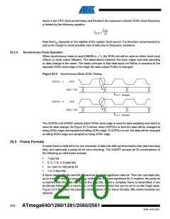
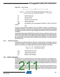
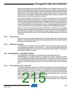
Figure 22-4. Frame Formats
FRAME
(IDLE)
St
0
1
2
3
4
[5]
[6]
[7]
[8]
[P] Sp1 [Sp2] (St / IDLE)
St
Start bit, always low.
Data bits (0 to 8).
(n)
P
Parity bit. Can be odd or even.
Stop bit, always high.
Sp
IDLE
No transfers on the communication line (RxDn or TxDn). An IDLE line
must be
high.
The frame format used by the USART is set by the UCSZn2:0, UPMn1:0 and USBSn bits in
UCSRnB and UCSRnC. The Receiver and Transmitter use the same setting. Note that changing
the setting of any of these bits will corrupt all ongoing communication for both the Receiver and
Transmitter.
The USART Character SiZe (UCSZn2:0) bits select the number of data bits in the frame. The
USART Parity mode (UPMn1:0) bits enable and set the type of parity bit. The selection between
one or two stop bits is done by the USART Stop Bit Select (USBSn) bit. The Receiver ignores
the second stop bit. An FE (Frame Error) will therefore only be detected in the cases where the
first stop bit is zero.
22.3.1
Parity Bit Calculation
The parity bit is calculated by doing an exclusive-or of all the data bits. If odd parity is used, the
result of the exclusive or is inverted. The parity bit is located between the last data bit and first
stop bit of a serial frame. The relation between the parity bit and data bits is as follows::
P
P
= d
= d
⊕ … ⊕ d ⊕ d ⊕ d ⊕ d ⊕ 0
3 2 1 0
even
n – 1
n – 1
⊕ … ⊕ d ⊕ d ⊕ d ⊕ d ⊕ 1
odd
3 2 1 0
Peven
Podd
dn
Parity bit using even parity
Parity bit using odd parity
Data bit n of the character
22.4 USART Initialization
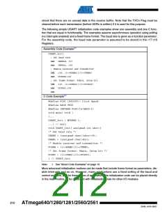
The USART has to be initialized before any communication can take place. The initialization pro-
cess normally consists of setting the baud rate, setting frame format and enabling the
Transmitter or the Receiver depending on the usage. For interrupt driven USART operation, the
Global Interrupt Flag should be cleared (and interrupts globally disabled) when doing the
initialization.
Before doing a re-initialization with changed baud rate or frame format, be sure that there are no
ongoing transmissions during the period the registers are changed. The TXCn Flag can be used
to check that the Transmitter has completed all transfers, and the RXC Flag can be used to
211
2549L–AVR–08/07

 ATMEL [ ATMEL ]