AT90PWM2/3/2B/3B
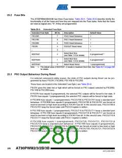
Notes: 1. “1” means unprogrammed, “0” means programmed.
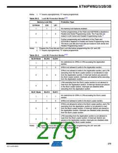
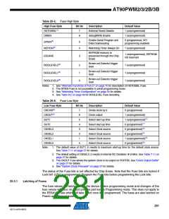
Table 25-2. Lock Bit Protection Modes(1)(2)
Memory Lock Bits
Protection Type
LB Mode
LB2
LB1
1
1
1
No memory lock features enabled.
Further programming of the Flash and EEPROM is disabled in
Parallel and Serial Programming mode. The Fuse bits are
locked in both Serial and Parallel Programming mode.(1)
2
1
0
0
0
Further programming and verification of the Flash and
EEPROM is disabled in Parallel and Serial Programming mode.
The Boot Lock bits and Fuse bits are locked in both Serial and
Parallel Programming mode.(1)
3
Notes: 1. Program the Fuse bits and Boot Lock bits before programming the LB1 and LB2.
2. “1” means unprogrammed, “0” means programmed
Table 25-3. Lock Bit Protection Modes(1)(2)
.
BLB0 Mode
BLB02
BLB01
No restrictions for SPM or LPM accessing the Application
section.
1
2
1
1
1
0
SPM is not allowed to write to the Application section.
SPM is not allowed to write to the Application section, and LPM
executing from the Boot Loader section is not allowed to read
from the Application section. If Interrupt Vectors are placed in
the Boot Loader section, interrupts are disabled while executing
from the Application section.
3
4
0
0
0
1
LPM executing from the Boot Loader section is not allowed to
read from the Application section. If Interrupt Vectors are placed
in the Boot Loader section, interrupts are disabled while
executing from the Application section.
BLB1 Mode
BLB12
BLB11
No restrictions for SPM or LPM accessing the Boot Loader
section.
1
2
1
1
1
0
SPM is not allowed to write to the Boot Loader section.
SPM is not allowed to write to the Boot Loader section, and LPM
executing from the Application section is not allowed to read
from the Boot Loader section. If Interrupt Vectors are placed in
the Application section, interrupts are disabled while executing
from the Boot Loader section.
3
4
0
0
0
1
LPM executing from the Application section is not allowed to
read from the Boot Loader section. If Interrupt Vectors are
placed in the Application section, interrupts are disabled while
executing from the Boot Loader section.
Notes: 1. Program the Fuse bits and Boot Lock bits before programming the LB1 and LB2.
2. “1” means unprogrammed, “0” means programmed
279
4317J–AVR–08/10

 ATMEL [ ATMEL ]