AT89S52
14. Oscillator Characteristics
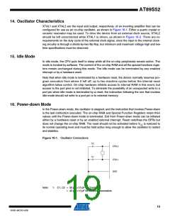
XTAL1 and XTAL2 are the input and output, respectively, of an inverting amplifier that can be
configured for use as an on-chip oscillator, as shown in Figure 16-1. Either a quartz crystal or
ceramic resonator may be used. To drive the device from an external clock source, XTAL2
should be left unconnected while XTAL1 is driven, as shown in Figure 16-2. There are no
requirements on the duty cycle of the external clock signal, since the input to the internal clock-
ing circuitry is through a divide-by-two flip-flop, but minimum and maximum voltage high and low
time specifications must be observed.
15. Idle Mode
In idle mode, the CPU puts itself to sleep while all the on-chip peripherals remain active. The
mode is invoked by software. The content of the on-chip RAM and all the special functions regis-
ters remain unchanged during this mode. The idle mode can be terminated by any enabled
interrupt or by a hardware reset.
Note that when idle mode is terminated by a hardware reset, the device normally resumes pro-
gram execution from where it left off, up to two machine cycles before the internal reset
algorithm takes control. On-chip hardware inhibits access to internal RAM in this event, but
access to the port pins is not inhibited. To eliminate the possibility of an unexpected write to a
port pin when idle mode is terminated by a reset, the instruction following the one that invokes
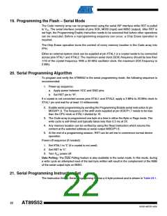
idle mode should not write to a port pin or to external memory.
16. Power-down Mode
In the Power-down mode, the oscillator is stopped, and the instruction that invokes Power-down
is the last instruction executed. The on-chip RAM and Special Function Registers retain their
values until the Power-down mode is terminated. Exit from Power-down mode can be initiated
either by a hardware reset or by an enabled external interrupt. Reset redefines the SFRs but
does not change the on-chip RAM. The reset should not be activated before VCC is restored to
its normal operating level and must be held active long enough to allow the oscillator to restart
and stabilize.
Figure 16-1. Oscillator Connections
C2
XTAL2
C1
XTAL1
GND
Note:
1. C1, C2 = 30 pF 10 pF for Crystals
= 40 pF 10 pF for Ceramic Resonators
19
1919D–MICRO–6/08

 ATMEL [ ATMEL ]