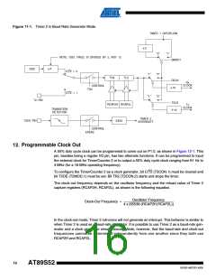
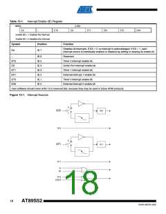
Figure 11-1. Timer 2 in Baud Rate Generator Mode
TIMER 1 OVERFLOW
2
÷
"0"
"0"
"1"
NOTE: OSC. FREQ. IS DIVIDED BY 2, NOT 12
SMOD1
RCLK
2
OSC
÷
C/T2 = 0
"1"
"1"
TH2
TL2
Rx
CLOCK
CONTROL
TR2
÷
16
C/T2 = 1
"0"
T2 PIN
TCLK
RCAP2H RCAP2L
Tx
CLOCK
TRANSITION
DETECTOR
16
÷
TIMER 2
INTERRUPT
T2EX PIN
EXF2
CONTROL
EXEN2
12. Programmable Clock Out
A 50% duty cycle clock can be programmed to come out on P1.0, as shown in Figure 12-1. This
pin, besides being a regular I/O pin, has two alternate functions. It can be programmed to input
the external clock for Timer/Counter 2 or to output a 50% duty cycle clock ranging from 61 Hz to
4 MHz (for a 16-MHz operating frequency).
To configure the Timer/Counter 2 as a clock generator, bit C/T2 (T2CON.1) must be cleared and
bit T2OE (T2MOD.1) must be set. Bit TR2 (T2CON.2) starts and stops the timer.
The clock-out frequency depends on the oscillator frequency and the reload value of Timer 2
capture registers (RCAP2H, RCAP2L), as shown in the following equation.
Oscillator Frequency
Clock-Out Frequency = ------------------------------------------------------------------------------------
4 x [65536-(RCAP2H,RCAP2L)]
In the clock-out mode, Timer 2 roll-overs will not generate an interrupt. This behavior is similar to
when Timer 2 is used as a baud-rate generator. It is possible to use Timer 2 as a baud-rate gen-
erator and a clock generator simultaneously. Note, however, that the baud-rate and clock-out
frequencies cannot be determined independently from one another since they both use
RCAP2H and RCAP2L.
16
AT89S52
1919D–MICRO–6/08

 ATMEL [ ATMEL ]