AT89S8252
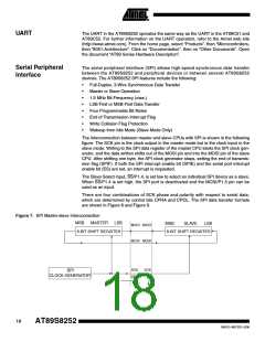
Figure 8. SPI transfer Format with CPHA = 0
Note:
*Not defined but normally MSB of character just received
Figure 9. SPI Transfer Format with CPHA = 1
SCK CYCLE #
1
2
3
4
5
6
7
8
(FOR REFERENCE)
SCK (CPOL=0)
SCK (CPOL=1)
MOSI
(FROM MASTER)
MSB
MSB
6
5
5
4
3
3
2
1
1
LSB
MISO
(FROM SLAVE)
6
4
2
LSB
*
SS (TO SLAVE)
Note:
*Not defined but normally LSB of previously transmitted character.
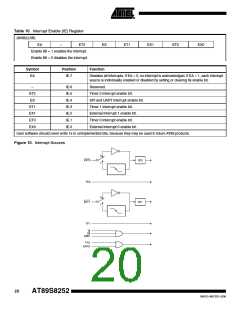
Interrupts
The AT89S8252 has a total of six interrupt vectors: two external interrupts (INT0 and
INT1), three timer interrupts (Timers 0, 1, and 2), and the serial port interrupt. These
interrupts are all shown in Figure 10.
Each of these interrupt sources can be individually enabled or disabled by setting or
clearing a bit in Special Function Register IE. IE also contains a global disable bit, EA,
which disables all interrupts at once.
Note that Table 10 shows that bit position IE.6 is unimplemented. In the AT89C51, bit
position IE.5 is also unimplemented. User software should not write 1s to these bit posi-
tions, since they may be used in future AT89 products.
Timer 2 interrupt is generated by the logical OR of bits TF2 and EXF2 in register
T2CON. Neither of these flags is cleared by hardware when the service routine is vec-
tored to. In fact, the service routine may have to determine whether it was TF2 or EXF2
that generated the interrupt, and that bit will have to be cleared in software.
The Timer 0 and Timer 1 flags, TF0 and TF1, are set at S5P2 of the cycle in which the
timers overflow. The values are then polled by the circuitry in the next cycle. However,
the Timer 2 flag, TF2, is set at S2P2 and is polled in the same cycle in which the timer
overflows.
19
0401G–MICRO–3/06

 ATMEL [ ATMEL ]