AT90USB64/128
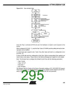
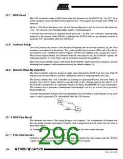
Figure 23-3. Pipe activation flow:
Pipe
Activ ation
UPCONX
PENABLE=1
Enablethepipe
SelectthePipetype:
UPCFG0X
PTYPE
PTOKEN
*Type(Control,Bulk,Interrupt)
*Token(IN,OUT ,SETUP)
*Endpointnumber
PEPNUM
UPCFG1X
ConfigurethePipememory:
*Pipesize
*Numberofbanks
PSIZE
PBK
CFGMEM
No
CFGOK=1
Yes
ERROR
UPCFG2X
INTFRQ
(interruptonly)
Configurethepollinginterval
forInterruptpipe
Pipeactiv ated
and f reezed
Once the Pipe is activated (EPEN set) and, the hardware is ready to send requests to the
Device.
When configured (CFGOK = 1), only the Pipe Token (PTOKEN) and the polling interval for Inter-
rupt pipe can be modified.
A Control type pipe supports only 1 bank. Any other value will lead to a configuration error
(CFGOK = 0).
A clear of PEN will reset the configuration of the Pipe. All the corresponding Pipe registers are
reset to there reset values. Please refers to the Memory Management chapter for more details.
Note: The firmware has to configure the Default Control Pipe with the following parameters:
• Type: Control
• Token: SETUP
• Data bank: 1
• Size: 64 Bytes
The firmware asks for 8 bytes of the Device Descriptor sending a GET_DESCRIPTOR request.
These bytes contains the MaxPacketSize of the Device default control endpoint and the firm-
ware re-configures the size of the Default Control Pipe with this size parameter.
295
7593A–AVR–02/06

 ATMEL [ ATMEL ]