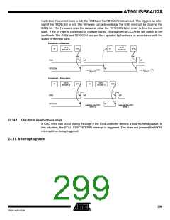
If the OUT Pipe is composed of multiple banks, this also switches to the next data bank. The
TXOUT and FIFOCON bits are automatically updated by hardware regarding the status of the
next bank.
Example with 1 OUT data bank
DATA
(bank 0)
OUT
ACK
HW
OUT
TXOUT
SW
SW
FIFOCON
SW
SW
write data from CPU
BANK 0
write data from CPU
BANK 0
Example with 2 OUT data banks
DATA
(bank 0)
DATA
(bank 1)
OUT
ACK
HW
OUT
ACK
TXOUT
SW
SW
SW
FIFOCON
SW
SW
write data from CPU
BANK 0
write data from CPU
BANK 1
write data from CPU
BANK0
Example with 2 OUT data banks
DATA
ACK
DATA
ACK
OUT
OUT
(bank 0)
(bank 1)
HW
TXOUT
SW
SW
SW
FIFOCON
SW
SW
write data from CPU
BANK 0
write data from CPU
BANK 1
write data from CPU
BANK0
23.14 IN Pipe management
The Pipe must be configured first.
When the Host requires data from the device, the firmware has to determine first the IN mode to
use using the INMODE bit:
• INMODE = 0. The INRQX register is taken in account. The Host controller will perform
(INRQX+1) IN requests on the selected Pipe before freezing the Pipe. This mode avoids to
have extra IN requests on a Pipe.
• INMODE = 1. The USB controller will perform infinite IN request until the firmware freezes the
Pipe.
The IN request generation will start when the firmware clear the PFREEZE bit.
298
AT90USB64/128
7593A–AVR–02/06

 ATMEL [ ATMEL ]