AT85C51SND3Bx
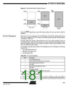
Figure 81. Nand Flash Write Protection Scheme
Block 0
FPB
Block 0
Block 0
LPB
protected
protected
FPB
LPB
LPB
FPB
protected
protected
FPB < LPB
FPB > LPB
FPB = LPB
Default
Since the NFWP signal state is part of the device status, the user can detect a fault be
reading it.
ECC Error Management
When an ECC error is detected, the ECCERRI flag is set in NFINT and the 4-byte ECC
error FIFO is updated. The FIFO content is read byte by byte using the NFERR register
as detailed in Table 199.
First byte of the FIFO returns a status if the error can or can not be corrected. If it can no
be corrected other 3-byte FIFO are cleared, If it can be corrected, the following 3 bytes
return the address of the byte in error within the page (2 bytes) and the address of the
bit in error within the byte (1 byte).
For example, if the byte read at offset 1921 (starting from 0) in a 2K page is E3 (wrong)
instead of A3:
•
•
•
byte offset MSB will be 07h
byte offset LSB will be 81h
bit offset will be 06h
Table 199. ECC Error Descriptor
Offset
Description
Error Identification Byte
0
Refer to Table 200 for information on byte content.
First 256-byte group of the sector
1
2
3
Byte offset
Second 256-byte group of the sector
Byte offset
Bit offset in the byte
Refer to Table 200 for information on byte content.
Table 200. ECC Error Identification Byte
7
6
5
4
3
2
1
0
0
0
0
0
SHERRID1 SHERRID0 FHERRID1 FHERRID0
181
7632A–MP3–03/06

 ATMEL [ ATMEL ]