AT7908E
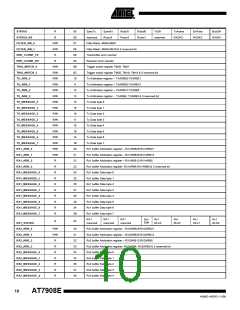
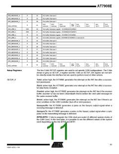
RX2_MESSAGE_5
RX2_MESSAGE_6
RX2_MESSAGE_7
R
R
R
39
3A
3B
Rx2 buffer Data byte 5
Rx2 buffer Data byte 6
Rx2 buffer Data byte 7
RX2
reserved
RX3
reserved
RX3
Reserved
Rx2
DLC3
Rx2
DLC2
Rx2
DLC1
Rx2
DLC0
RX2
Extfr
R
3C
RX2_STATUS
RX3_ARB_0
R/W
R/W
R
40
41
42
43
44
45
46
47
48
49
4A
4B
Rx3 buffer Arbitration register – RX3ARB28:RX3ARB21
Rx3 buffer Arbitration register – RX3ARB20:RX3ARB13
Rx3 buffer Arbitration register – RX3ARB12:RX3ARB5
RX3_ARB_1
RX3_ARB_2
RX3_ARB_3
R
Rx3 buffer Arbitration register- RX3ARB4:RX3ARB0 & 3 reserved bit
Rx3 buffer Data byte 0
RX3_MESSAGE_0
RX3_MESSAGE_1
RX3_MESSAGE_2
RX3_MESSAGE_3
RX3_MESSAGE_4
RX3_MESSAGE_5
RX3_MESSAGE_6
RX3_MESSAGE_7
R
R
Rx3 buffer Data byte 1
R
Rx3 buffer Data byte 2
R
Rx3 buffer Data byte 3
R
Rx3 buffer Data byte 4
R
Rx3 buffer Data byte 5
R
Rx3 buffer Data byte 6
R
Rx3 buffer Data byte 7
RX3
reserved
RX3
reserved
RX3
reserved
Rx3
DLC3
Rx3
DLC2
Rx3
DLC1
Rx3
DLC0
RX3
Extfr
R
4C
RX3_STATUS
Setup Registers
The five 8 bits SETUP registers are used to set specific CAN configurations. The 5 bits
shown in grey on SETUP_3 register and the 3 bits on SETUP_RX register are not writ-
ten directly inside the interface but are used to perform reset or other actions.
SETUP_0 :
Txint: active high, the AT7908E generates the interrupt on the INT line after a success-
ful transmission.
Rxint: active high, the AT7908E generates one interrupt on the INT line after a success-
ful data frame reception.
Overint: active high, the AT7908E generates the interrupt on the INT line if the receiver
buffer (number n) has not been cleared(with RxClr) before the next valid message for
the same receiver buffer.
Errint: active high, the AT7908E generates the interrupt on the INT line if there’s an
error condition on the CAN Controller (bus-off or error-passive).
GensyncRx: the AT7908E generates a pulse on the hasync output signal when a
receiving message is detected.
GensyncTx: the AT7908E generates a pulse on the hasync output signal when a sync
pulse on the transmitting message is detected.
BPR0-BPR1: 2 bits to program the CAN clock pre-scaler (4 different system clocks of
the CAN Core). In the next table, it is possible to see the different values of the system
clock depending on the bits BPR0 and BPR1.
11
4268D–AERO–11/09

 ATMEL [ ATMEL ]