29C516E
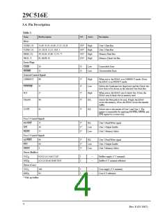
3.4. Pin Description
Table 1:
Name
Pin Description
I/O
Active
Description
Buses
U1D[0..15]
U2D[0..15]
ΜD[0..15]
ΜC[0..7]
Error Flags
CERR
53,49..47,45..42,40..37,35..33,28
23..20,18..15,13..10,8..5
59..62,64..67,69..72,74..77
83..86,88..91
I/O*
I/O*
I/O*
I/O*
High
High
High
High
User 1 Data Bus
User 2 Data Bus
Memory Data Bus
Memory Check–bit Bus
26
25
O
O
Low
Low
Correctable Error
NCERR
Uncorrectable Error
General Control Signals
CORRECT
SYNCHK
N22
98
97
27
96
I*
I*
I*
I*
High
Low
High
H/L
When active, the EDAC is in CORRECT mode. If low,
the EDAC is in DETECT mode.
Selects the Syndrome bits (high byte) and the Check–bits
(low byte) to be driven on the selected User Data Bus.
When active, the EDAC uses 6 check–bits. If low, the
EDAC uses 8 check–bits in memory read.
TRANS
Selects the Data path to be used. If high, the EDAC
access the memory, if low, the EDAC access the transfer
buffer.
U2/U1
95
I*
H/L
Selects who is the master of User 1 and User 2. The
master is responsible for applying RD/WRx, MEMx, and
ENx signals in a correct way.
User 1 Control Signals
RD/WRT
EN1
55
56
57
I*
I*
I*
H/L
Low
Low
User 1 Read/Write signal
User 1 Output Enable
User 1 Memory Select
MEM1
User 1 Control Signals
RD/WR2
EN2
99
94
3
I*
I*
I*
H/L
Low
Low
User 2 Read/Write signal
User 2 Output Enable
User 2 Memory Select
MEM2
Power (Buffers)
VCC
9,19,32,41,54,63,73,87
I
I
–
–
Buffers supply (5 V nominal)
Buffers 0 V nominal reference
B
GND
4,14,24,36,46,58,68,78,92
B
Power (Core)
VCC
100
93
I
I
–
–
Core supply (5 V nominal)
Core 0 V reference
C
GND
C
* Pull–up buffers
4
Rev. E (03 2007)

 ATMEL [ ATMEL ]