Torwards
AT8563
be set. This will indicate that the time may have been corrupted.
Fig 4 Voltage-low detection
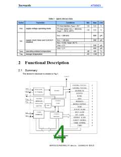
2.7 Register organization
Table 4 Registers overview
Address
Register name
b7
b6
b5
b4
b3
b2
b1
b0
00H
01H
0DH
0EH
Control/Status 1
Control/Status 2
CLKOUT frequency
Timer control
TEST1
0
0
0
-
STOP
0
TESTC
0
TF
-
0
0
0
-
TI/TP
AF
AIE
TIE
FE
-
-
-
-
FD1 FD0
TD1 TD0
TE
-
-
-
0FH
Timer countdownvalue
<timer countdown value>
Note: Bit positions labeled as ‘− ’are not implemented; those labeled with ‘0’ should always be written with
logic 0.
Table 5 BCD formatted registers overview
Address
Register name
b7
b6
b5
b4
b3
b2
b1
b0
Seconds
minutes
hours
02H
03H
04H
05H
06H
VL
-
-
-
-
ten seconds(0-5)
ten minutes(0-5)
seconds(0-9)
minutes(0-9)
hours(0-9)
days(0-9)
-
-
-
ten hours(0-2)
ten days(0-3)
days
weekday
-
-
-
-
weekdays(0-6)
month(0-9)
ten month
07H
months/century
C
-
(0-1)
08H
09H
0AH
0BH
0CH
years
ten years(0-9)
years(0-9)
minutes(0-9)
hours(0-9)
———
minute alarm
hour alarm
day alarm
ten minutes(0-5)
AE
———
-
-
-
ten hours(0-2)
ten days(0-3)
AE
———
days(0-9)
AE
———
weekday alarm
-
-
-
weekdays(0-6)
AE
Note: Bit positions labelled as ‘− ’are not implemented.
•
5
•
圳市宏达科技有限公司 Mobile:13530382140 曾先生

 Narda-ATM [ Narda-ATM ]