AX88179
USB 3.0 to 10/100/1000M Gigabit Ethernet Controller
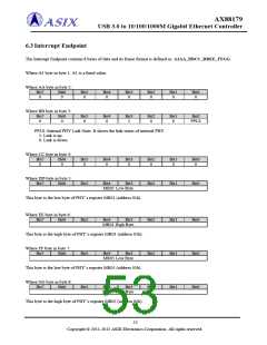
6.3 Interrupt Endpoint
The Interrupt Endpoint contains 8 bytes of data and its frame format is defined as: A1AA_BBCC_DDEE_FFGG.
Where A1 byte in byte 1: A1 is a fixed value.
Where AA byte in byte 2:
Bit7
0
Bit6
0
Bit5
0
Bit4
0
Bit3
0
Bit2
0
Bit1
0
Bit0
0
Where BB byte in byte 3:
Bit7
0
Bit6
0
Bit5
0
Bit4
0
Bit3
1
Bit2
0
Bit1
0
Bit0
PPLS
PPLS: Internal PHY Link State. It shows the link status of internal PHY.
1: Link is up.
0: Link is down.
Where CC byte in byte 4:
Bit7
0
Bit6
0
Bit5
0
Bit4
0
Bit3
0
Bit2
0
Bit1
0
Bit0
0
Where DD byte in byte 5:
Bit7 Bit6
Bit5
Bit4
Bit3
Bit2
Bit1
Bit0
MR01 Low Byte
This byte is the low byte of PHY’s register MR01 (address 01h).
Where EE byte in byte 6:
Bit7
Bit6
Bit5
Bit4
Bit3
Bit2
Bit2
Bit2
Bit1
Bit1
Bit1
Bit0
Bit0
Bit0
MR01 High Byte
This byte is the high byte of PHY’s register MR01 (address 01h).
Where FF byte in byte 7:
Bit7
Bit6
Bit5
Bit4
MR05 Low Byte
Bit3
This byte is the low byte of PHY’s register MR05 (address 05h).
Where GG byte in byte 8:
Bit7
Bit6
Bit5
Bit4
Bit3
MR05 High Byte
This byte is the high byte of PHY’s register MR05 (address 05h).
52
Copyright © 2011-2012 ASIX Electronics Corporation. All rights reserved.

 ASIX [ ASIX ELECTRONICS CORPORATION ]