AOZ1282CI
The AOZ1282CI has internal short circuit protection to
protect itself from catastrophic failure under output short
circuit conditions. The FB pin voltage is proportional to
the output voltage. Whenever FB pin voltage is below
0.2V, the short circuit protection circuit is triggered. As a
result, the converter is shut down and hiccups. The
converter will start up via a soft start once the short circuit
condition disappears. In short circuit protection mode, the
inductor average current is greatly reduced.
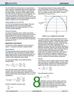
The relationship between the input capacitor RMS
current and voltage conversion ratio is calculated and
shown in Figure 2. It can be seen that when V is half of
O
V , C is under the worst current stress. The worst
IN
IN
current stress on C is 0.5 x I .
IN
O
0.5
0.4
0.3
0.2
0.1
0
Under Voltage Lock Out (UVLO)
ICIN_RMS(m)
IO
An UVLO circuit monitors the input voltage. When the
input voltage exceeds 2.9V, the converter starts
operation. When input voltage falls below 2.3V, the
converter will stop switching.
Thermal Protection
0
0.5
m
1
An internal temperature sensor monitors the junction
temperature. It shuts down the internal control circuit and
high side NMOS if the junction temperature exceeds
150ºC. The regulator will restart automatically under the
control of soft-start circuit when the junction temperature
decreases to 110°C.
Figure 2. ICIN vs. Voltage Conversion Ratio
For reliable operation and best performance, the input
capacitors must have current rating higher than I
CIN-RMS
at worst operating conditions. Ceramic capacitors are
preferred for input capacitors because of their low ESR
and high ripple current rating. Depending on the
application circuits, other low ESR tantalum capacitor or
aluminum electrolytic capacitor may also be used. When
selecting ceramic capacitors, X5R or X7R type dielectric
ceramic capacitors are preferred for their better
temperature and voltage characteristics. Note that the
ripple current rating from capacitor manufactures is
based on certain amount of life time. Further de-rating
may be necessary for practical design requirement.
Application Information
The basic AOZ1282CI application circuit is shown in
Figure 1. Component selection is explained below.
Input Capacitor
The input capacitor must be connected to the VIN pin
and PGND pin of the AOZ1282CI to maintain steady
input voltage and filter out the pulsing input current. The
voltage rating of input capacitor must be greater than
maximum input voltage plus ripple voltage.
Inductor
The input ripple voltage can be approximated by
equation below:
The inductor is used to supply constant current to output
when it is driven by a switching voltage. For given input
and output voltage, inductance and switching frequency
together decide the inductor ripple current, which is:
I
V
V
O
O
O
-----------------
--------
--------
V
=
1 –
IN
f C
V
V
IN
IN
IN
V
V
O
O
----------
--------
I
=
1 –
L
f L
Since the input current is discontinuous in a buck
converter, the current stress on the input capacitor is
another concern when selecting the capacitor. For a buck
circuit, the RMS value of input capacitor current can be
calculated by:
V
IN
The peak inductor current is:
I
L
--------
I
= I +
Lpeak
O
2
V
V
O
O
--------
--------
I
= I
1 –
CIN_RMS
O
V
V
High inductance gives low inductor ripple current but
requires larger size inductor to avoid saturation. Low
ripple current reduces inductor core losses. It also
reduces RMS current through inductor and switches,
which results in less conduction loss.
IN
IN
if we let m equal the conversion ratio:
V
O
--------
= m
V
IN
Rev. 0.5 September 2012
www.aosmd.com
Page 8 of 13

 AOS [ ALPHA & OMEGA SEMICONDUCTORS ]