AOZ1282CI
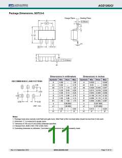
Package Dimensions, SOT23-6
Gauge Plane
c
Seating Plane
0.25mm
D
e1
L
E
E1
θ1
b
e
A2
A
.010mm
A1
Dimensions in millimeters
Dimensions in inches
Symbols Min.
Nom. Max.
Symbols Min.
Nom. Max.
RECOMMENDED LAND PATTERN
A
A1
A2
b
c
D
E
E1
e
0.90
0.00
0.70
0.30
0.08
2.70
2.50
1.50
—
—
1.10
0.40
0.13
2.90
2.80
1.60
1.25
0.15
1.20
0.50
0.20
3.10
3.10
1.70
A
A1
A2
b
c
D
E
E1
e
0.035
0.00
—
—
0.049
0.006
1.20
0.028 0.043 0.047
0.012 0.016 0.020
0.003 0.005 0.008
0.106 0.114 0.122
0.098 0.110 0.122
0.059 0.063 0.067
0.037 BSC
2.40
0.80
0.95
0.63
0.95 BSC
1.90 BSC
—
UNIT: mm
e1
L
θ1
e1
L
θ1
0.075 BSC
0.30
0°
0.60
8°
0.012
0°
—
—
0.024
8°
—
Notes:
1. Package body sizes exclude mold flash and gate burrs. Mold flash at the non-lead sides should be less than 5 mils each.
2. Dimension “L” is measured in gauge plane.
3. Tolerance 0.100 mm (4 mil) unless otherꢀise specified.
4. Folloꢀed from JEDEC MO-178C & MO-193C.
5. Controlling dimension is millimeter. Converted inch dimensions are not necessarily exact.
Rev. 0.5 September 2012
www.aosmd.com
Page 11 of 13

 AOS [ ALPHA & OMEGA SEMICONDUCTORS ]