APW7108
Function Description (Cont.)
Power Good Indicator
Both PWM controllers use the low-side MOSFETs on-re-
sistance RDS(ON), to monitor the current for protection
against shortened outputs. The sensed current from
the ISEN pin is compared with a current set by a resis-
tor connected from the OCSET pin to the ground:
In the soft-start process, the PGOOD is an open-drain and
established after the soft pin voltage is above 1.5V. In
normal operation, the PGOOD window is from 89% to
115% of the converter’s reference voltage. The VSEN
pin has to stay within this window for PGOOD to be high.
Since the VSEN pin is used for both feedback and moni-
toring purposes, the output voltage deviation can be coupled
directly to the VSEN pin by the capacitor in parallel with the
voltage divider as shown in the typical applications. In order
to prevent false PGOOD drop, capacitors need to parallel
at the output to confine the voltage deviation with se-
vere load step transient. The PGOOD comparator has
a built-in 3µs noise filter.
10.3
OC ×RDS(ON)
ROCSET
=
I
+ 8mA
RISEN+140W
where, IOC is a desired current-limit threshold and RISEN
is the value of the current sense resistor con-
nected to the ISEN pin. The 8µA is the offset current
added on top of the sensed current from the ISEN pin for
internal circuit biasing.
When POR=0, EN= 0, or after UVP, the PGOOD is
pulled low regardless of the output voltage.
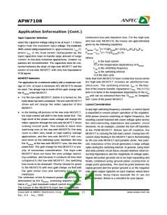
IPEAK
IOUT
EnableControl
When the EN pin is high (EN=1), the PWM is enabled and
the soft-start is initiated. When both EN1 and EN2 are low
(EN=0), the chip is in the shutdown and only low leakage
current is taken from VCC and VIN. In shutdown mode,
LGATE will be pulled high.
IOC
0
Time
Figure 1. Current Limit Algorithm
Current-Limit
The current-limit circuit employs an unique “valley” cur-
rent sensing algorithm (Figure 1). If the magnitude of the
current-sense signal at ISEN pin is above the cur-
rent-limit threshold, the PWM is not allowed to initiate a
new cycle. The actual peak current is greater than the cur-
rent-limit threshold by an amount equals to the inductor
ripple current. Therefore, the exact current-limit charac-
teristic and maximum load capability are the function of the
sense resistance, inductor value, and battery voltage.
The current sensing pin can source up to 260µA. The
current sense resistor RISEN and OCSET resistor ROCSET
can be adjusted simultaneously for the same current-limit
threshold level. The relationship between the sampled
current and MOSFET current is given by:
ISEN(RISEN +140) = RDS(ON) ×ID
Which means the current sensing pin will source
current to make the voltage drop on the MOSFET equals
to the voltage generated on the sensing resistor, plus the
internal resistor, along the ISEN pin current flowing path.
Copyright ã ANPEC Electronics Corp.
19
www.anpec.com.tw
Rev. A.4 - Jan., 2009

 ANPEC [ ANPEC ELECTRONICS COROPRATION ]