APA2065
Application Descriptions (Cont.)
VOLUME input pin. The APA2065 volume control
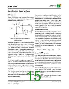
Output SE/BTL Operation (Cont.)
consists of 32 steps that are individually selected by
a variable DC voltage level on the VOLUME control
pin. The range of the steps, controlled by the DC
voltage, are from 20dB to -80dB. Each gain step
correspondstoaspecificinputvoltagerange,asshown
in table. To minimizethe effect of noise onthe volume
control pin, which can affect the selected gain level,
hysteresis and clock delay are implemented. The
amount of hysteresis corresponds to half of the step
width, as shown in volume control graph.
· When SE/BTL is held high, the OP2 is in a high
output impedance state, which configures the
APA2065 as SE driver from OUT+. IDD is reduced by
approximately one-half in SE mode.
Control of the SE/BTL input can be a logic-level TTL
sourceor aresistor divider networkor the stereohead-
phone jack with switch pin as shown in Application
Circuit.
Gani_BTLmode
20
APA2021volumecontrolcurve
1kW
Forward
Backward
VDD
16
12
8
Control
Pin
Ring
100kW
SE/BTL
4
0
-4
-8
Sleeve
Tip
Headphone Jack
-12
-16
-20
-24
-28
-32
-36
-40
-44
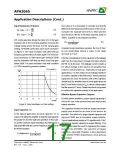
Figure 2: SE/BTL input selection by phonejack plug
In Figure 2, input SE/BTL operates as follows :
When the phonejack plug is inserted, the 1kW resistor
is disconnected and the SE/BTL input is pulled high
and enables the SE mode. When the input goes high,
the OUT- amplifier isshutdown causing the speaker to
mute. The OUT+ amplifier then drives through the
output capacitor (CC) into the headphone jack. When
there is no headphone plugged into the system, the
contact pin of the headphone jack is connected from
0
0.2 0.4
0.6
0.8
1
1.2 1.4
1.6
1.8
2
2.2
2.4 2.6
2.8
3
3.2
3.4 3.6 3.8
(V)
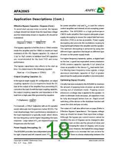
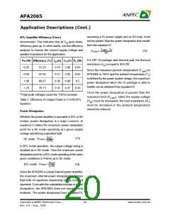
Figure 3: Gain setting vsVOLUME pin voltage
For highest accuracy, the voltage shown in the
‘recommended voltage’ column of the table is used
to select a desired gain. This recommended voltage
is exactly halfway betweenthe twonearest transitions.
The gain levels are 2dB/step from 20dB to -40dB in
BTL mode, and the last step at -80dB as mute mode.
thesignalpin,the voltage divider set up by resistors
100kW and 1kW.
Resistor 1kW then pulls low the SE/BTL pin, enabling
Input Resistance, Ri
the BTL function.
The gain for each audio input of theAPA2065 isset by
the internal resistors (Ri and Rf) of volume control
amplifier ininverting configuration.
Volume Control Function
APA2065 hasan internal stereo volume control whose
setting is a function of the DC voltage applied to the
Copyright ã ANPEC Electronics Corp.
16
www.anpec.com.tw
Rev. A.4 - Aug., 2005

 ANPEC [ ANPEC ELECTRONICS COROPRATION ]