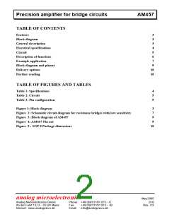
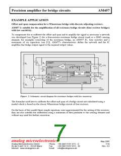
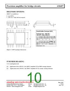
Precision amplifier for bridge circuits
AM457
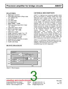
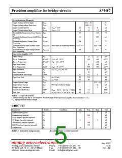
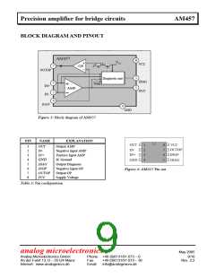
BLOCK DIAGRAM AND PINOUT
AM457
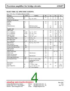
8
VCC
VCC
7
3
OP
1k
9k
OUTOP
5
1
Diagnostic unit
DIAG
OUT
Temp
IN+
IN-
AMP
2
6
4
GND
Figure 3: Block diagram of AM457
PIN
NAME
EXPLANATION
Output AMP
Negative Input AMP
Positive Input AMP
IC Ground
8
7
6
5
OUT
IN-
IN+
VCC
OUTOP
INOP
DIAG
1
2
3
4
1
2
3
4
5
6
7
8
OUT
IN-
IN+
GND
DIAG
INOP
OUTOP
VCC
GND
Output Diagnosis
Negative Input OP
Output OP
Figure 4: AM457 Pin out
Supply Voltage
Table 3: Pin configuration
analog microelectronics
May 2005
Analog Microelectronics GmbH
An der Fahrt 13, D – 55124 Mainz
Internet: www.analogmicro.de
Phone: +49 (0)6131/91 073 – 0
9/10
Fax:
+49 (0)6131/91 073 – 30
Rev. 2.2
Email: info@analogmicro.de

 AME [ ANALOG MICROELECTRONICS ]