Precision amplifier for bridge circuits
AM457
The formulae used are:
2 ⋅RB
5⋅dRS
R1 = R2 =
(kΩ)
Span adjustment (1)
R1
R4 =
(kΩ)
Auxiliary resistor (2)
Offset adjustment (3)
100
(−8⋅dRO+dRS) ⋅R4
8⋅dRO +9 ⋅dRS
R3 =
(kΩ)
whereby the following applies to the individual sensing elements:
RB – Bridge resistance in ohms
dRS – Span/supply voltage in mV/V
dRO – Offset/supply voltage in mV/V
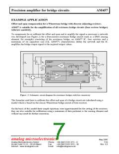
In order to calculate the discrete adjusting resistors R1, R2, R3 and R4 the offset, span and bridge
resistance of the sensing element to be calibrated are first determined. The sensing element is then
connected up to an AM457 to form the circuit illustrated in Figure 2. The resistors are dimensioned
and applied according to the given formulae. The values of the capacitors are selected according to
Table 1. (Capacitors C3…C6 are designated as decoupling capacitors; their use is therefore optional.)
Using the calculated resistances and the given capacitors the offset and span (0.5...4.5V) should
now be set. Discrepancies between the resistors used and the theoretical value enter the offset error
proportionally.
The calibration suggested in this article is suitable and has a sufficient accuracy for all sensing
elements
• which consist of four bridge resistors
• which permit calibration with discrete resistors
• which have a sensitivity of ±5…±100mV FS
• where the span signal is greater than the offset.
Depending on the level of accuracy required, when using sensing elements which have additional
resistors (such as ceramic sensing elements for offset correction, for example) the discrete adjusting
resistors must be corrected due to the discrepancy between the model and the sensing element (see
[2]).
analog microelectronics
May 2005
Analog Microelectronics GmbH
An der Fahrt 13, D – 55124 Mainz
Internet: www.analogmicro.de
Phone: +49 (0)6131/91 073 – 0
Fax: +49 (0)6131/91 073 – 30
Email: info@analogmicro.de
8/10
Rev. 2.2

 AME [ ANALOG MICROELECTRONICS ]