P R E L I M I N A R Y
Note: The IMR2 device only supports Normal operation.
PAUI Ports
Full-Duplex Mode
The PAUI ports are functionally equivalent to AUI ports
as described in IEEE 802.3, Section 7. However, they
are single ended and, therefore, are not an exact match
with the electrical specifications.
In Full-Duplex mode a port can transmit and receive simul-
taneously, and Collision and PAUI Loopback functions are
disabled.The normal loopback of PDO to PDI is disabled
to allow the RXD signal to be transmitted on PDI.
PDO, PDI, and PCI are functionally similar to DO, DI,
and CI, respectively. PDO is the PAUI input from the
IMR2 device. This signal is transmitted by the corre-
sponding TXD port. PDI is the data output to the IMR2
device and is the data received by the corresponding
RXD port. PDI also loops back data received by PDO
to the IMR2 device. PCI is the collision output to the
IMR2 device and indicates either a collision on the cor-
respondingportoranexcessivecontinuousdatastream
on the corresponding PDO.PCI sends a 10-MHz square
wave during collision and jabber.
PCI is disabled and Jabber status is only available to
the controller through the serial management interface.
The serial management interface also transmits Jabber
status when the QuIET device is in Normal mode.
Serial Management Interface
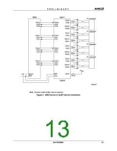
Command and status data are transferred between the
QuIET device and the IMR2 device via SDATA. (See
Figure 4 for proper interconnections.) The direction of
SDATA is set by DIR. All activity on SDATA starts at the
edge (rising or falling) of DIR.
Collision Handling
The DIR pin of the QuIET device connects to DIR[1] of
the IMR2 device. The IMR2 device continually cycles
DIR[1] LOW and HIGH.LOW is status reporting (SDATA
Write) and HIGH is management commands (SDATA
Read). The controller (IMR2 device) should keep DIR
at one level for the entire bit stream. The status bit
stream is described in theStatus Reporting section, and
the command bit stream is described in the Manage-
ment Commands section. Each bit on SDATA is held for
2-bit times (200 ns).
Collision is defined for the QuIET device as data being
simultaneously transmitted and received at the corre-
sponding TXD and RXD pins. When a collision is de-
tected, the QuIET device sends a 10 MHz signal over
the corresponding PCI pin.This is the only action taken
by the QuIET device. The generation of the JAM signal
is performed by the IMR2 device.
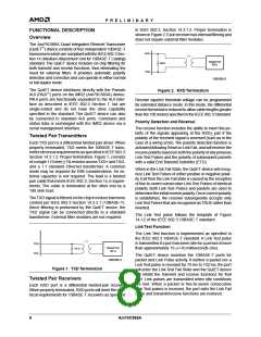
Jabber Protection
The Jabber function inhibits the twisted pair transmit
function of the port if the PDO circuit is active for an
excessive period (> 30 ms). If the maximum transmit
time is exceeded, the transmitter circuitry is disabled,
PDO to PDI loopback is disabled, and a 10 MHz signal
is transmitted by PCI. Once the data stream is removed
from PDO, 350 ms will elapse before PCI stops trans-
mitting the 10 MHz signal and the TXD circuitry is en-
abled again. Note that a properly functioning repeater
device will never jabber because of the MAU Jabber
Lockup Protection (MJLP).
Status Reporting
When DIR switches from HIGH to LOW, the QuIET de-
vice drives SDATA with status information (left to right)
in the format shown below. After the 29th bit, the SDATA
driver turns off. The SDATA driver also turns off if DIR
switches HIGH before the 29th bit.
Status Information Format
01010A A A A B B B B C C C C D D D D SSSSSSSS
0
1 2 3 0 1 2 3 0 1 2 3 0 1 2 3
Transceiver Modes
01010
Preamble
QuIET device ID (0000 for QuIET device)
The QuIET transceivers have two modes of operation:
Normal and Full Duplex.In Normal mode, the data flows
only in one direction at a time. In Full-Duplex mode, the
collision circuitry and the loopback circuitry are dis-
abled.Therefore, transmit and receive can occur simul-
taneously.The transceiver mode is selected through the
serial management interface, which is explained further
in the Management Commands and Transceiver Mode
Selection sections.
A
n
n
B
0
1
0
1
0
1
Link Fail
Link Pass
C
D
S
Received Polarity Reversed
Received Polarity Correct
No Jabber
n
n
Jabber
Not used, logic HIGH
Normal Mode
Preamble
The QuIET device defaults to the Normal mode at power
up and reset. In this mode, no twisted pair port can
transmit and receive data simultaneously. If a port re-
ceives data when it is transmitting, the QuIET device
sends a collision signal to the IMR2 device via the cor-
responding PCI pin.
The 01010 preamble is an indication to the IMR2 that
the transceiver is a QuIET device.
QuIET Device ID
A A A A
1 2 3
0
The QuIET device returns 0000.
Am79C988A
9

 AMD [ AMD ]