P R E L I M I N A R Y
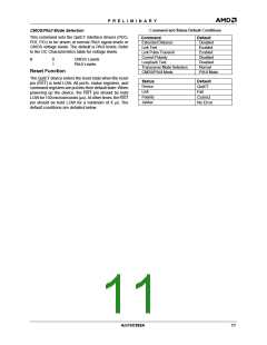
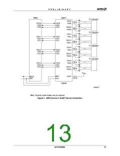
10BASE-T ports that can be individually switched be-
SYSTEMS APPLICATIONS
10BASE-T Repeaters
tween three Ethernet collision domains.
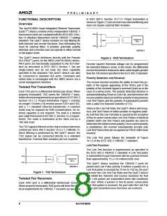
The IMR2 and QuIET devices must share a common
ground plane and a common power plane. Failure to
meet this design requirement may result in false asser-
tion of internal carrier sense or inability to unsquelch in
either PDI (for IMR2) or PDO (for QuIET).
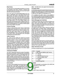
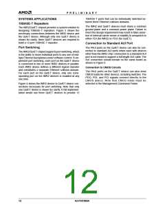
The IMR2/QuIET chipset provides a system solution to
designing 10BASE-T repeaters. Figure 3 shows the
necessary connections between the IMR2 device and
the QuIET device. Although only one QuIET device is
shown for clarity, three QuIET devices are required to
build a 12-port 10BASE-T repeater.
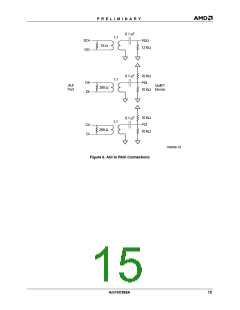
Connection to Standard AUI Port
Port Switching
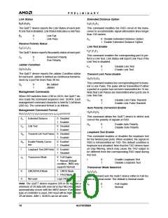
The PAUI ports on the QuIET device can also be con-
nected to standard AUI ports when used with devices
other than the IMR2 chip. Connection to a standard AUI
port is not meant to support a full length AUI cable.The
AUI connection should remain on the same board as
shown in Figure 6.
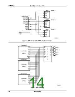
TheIMR2/QuIETchipsetsupportsportswitching, which
is the ability to move individual ports to any one of mul-
tiple Ethernet backplanes under software control.To im-
plement port switching, each port on the QuIET device
is connected to two or more IMR2 devices in parallel.
Each IMR2 device defines a different logical repeater
and constitutes a separate Ethernet collision domain.
For each port on the QuIET device, only one corre-
sponding port on the IMR2 devices is enabled at any
one time.
Connection to CMOS Circuits
The PAUI ports on the QuIET device can also drive
CMOS loads for other devices, including switches. The
PDO, PDI, and PCI signals connect directly to the
CMOS device. Note that CMOS mode must be
selected in the Management Command Frame.
Figure 4 shows the IMR2 device-to-QuIET device con-
nections necessary for port switching. Note that only
one QuIET device is shown for clarity. A full implemen-
tation would use three QuIET devices to provide 12
12
Am79C988A

 AMD [ AMD ]