PULSE_POSITION_0 occurs at a value defined in
Table 13 which determines the transmission speed.
When a pulse begins transmission, the previous sym-
bol interval ends and a new one begins immediately.
Data Symbols
Data symbols encode data for a much higher transmis-
sion rate, and they do not allow collision detection.
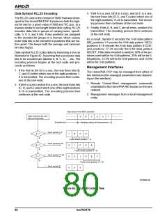
Data Transmit Timing
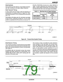
Table 13. Blanking Interval Speed Settings
PULSE_POSITION_0
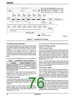
A data symbol interval begins with the beginning of
transmission of a pulse as shown in Figure 40. Trans-
mit Symbol timing (in TICS) is measured from this point
(TIC = 0).
Nominal Data
Rate
Value
(in TICs)
Speed Setting
LOW_SPEED
HIGH_SPEED
0.7 Mbps
1.0 Mbps
44
28
Depending on the data code, the next pulse may begin
at any PULSE_POSITION_N where N = 0 to 24. Each
position is separated from the previous one by one TIC.
Transmitter
Symbol 1
Symbol 2
1 TIC
Pulse 0
Data Blanking interval (DISBI)
Pulse 1
Pulse 2
START_TX_PULSE END_TX_PULSE
TIC=0 time
PULSE_POSITION_0
time
Position 1 Position n1
n=0-24
Position 0
Position 1
Position n2
22206B-44
Figure 40. Transmit Data Symbol Timing
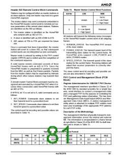
The receiver is then re-enabled for pulse detection.
Upon reception of the next pulse, the receiver mea-
sures the elapsed time from the previous pulse. This
value is then placed in the nearest pulse position bin
(one of 25) where pulse position 0 is at
PULSE_POSITION_0 and each subsequent position is
spaced one TIC from the previous one as defined in the
Data Transmit Timing section. Data symbol intervals
are therefore variable and depend on the encoded
data.
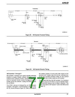
Data Receive Timing
The incoming waveform is formed from the transmitted
pulse. The receiver detects the point at which the enve-
lope of the received waveform crosses a set threshold.
See Figure 41.
Immediately after the threshold crossing, the receiver
disables any further detection for a period ISBI-3 TICs
(HPR28 ISBI_SLOW or ISBI_FAST) starting with the
detection of the pulse peak.
Receiver
Symbol 1
Symbol 2
Pulse 0
Pulse 1
Pulse 2
Data slice
threshold
Detected Envelope
END_DATA_BLANK
Begin of receive
Blanking interval
Position 0
Position 1 Position n1
Position 0
Position 1
Position n2
22206B-45
Figure 41. Receive Symbol Timing
Am79C978
79

 AMD [ AMD ]