TheAm79C978 controller will reset all CSR locations to
their STOP_RESET values. The BCR and PCI config-
uration registers will not be cleared. Any on-going net-
work transmission is terminated in an orderly
sequence. If less than 512 bits have been transmitted
onto the network, the transmission will be terminated
immediately, generating a runt packet. If 512 bits or
more have been transmitted, the message will have the
current FCS inverted and appended at the next byte
boundary to guarantee an FCS error is detected at the
receiving station.
CLK
2
3
4
5
6
7
1
FRAME
ADDR
0111
DATA
AD
C/BE
PAR
0000
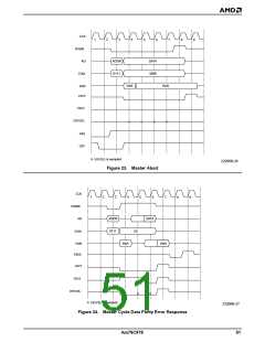
RMABORT (in the PCI Status register, bit 13) will be set
to indicate that the Am79C978 controller has termi-
nated its transaction with a master abort. In addition,
SINT (CSR5, bit 11) will be set to 1. When SINT is set,
INTA is asserted if the enable bit SINTE (CSR5, bit 10)
is set to 1. This mechanism can be used to inform the
driver of the system error. The host can read the PCI
Status register to determine the exact cause of the in-
terrupt. See Figure 23.
PAR
PAR
IRDY
TRDY
DEVSEL
Parity Error Response
STOP
REQ
During every data phase of a DMA read operation,
when the target indicates that the data is valid by as-
serting TRDY, the Am79C978 controller samples the
AD[31:0], C/BE[3:0], and the PAR lines for a data parity
error. When it detects a data parity error, the
Am79C978 controller sets PERR (PCI Status register,
bit 15) to 1. When reporting of that error is enabled by
setting PERREN (PCI Command register, bit 6) to 1,
the Am79C978 controller also drives the PERR signal
low and sets DATAPERR (PCI Status register, bit 8) to
1. The assertion of PERR follows the corrupted data/
byte enables by two clock cycles and PAR by one clock
cycle.
GNT
DEVSEL is sampled
22206B-23
Figure 20. Target Abort
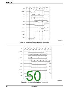
When the preemption occurs after the counter has
counted down to 0, the Am79C978 controller will finish
the current data phase, deassert FRAME, finish the
last data phase, and release the bus. Note that it is im-
portant for the host to program the PCI Latency Timer
according to the bus bandwidth requirement of the
Am79C978 controller. The host can determine this bus
bandwidth requirement by reading the PCI MAX_LAT
and MIN_GNT registers.
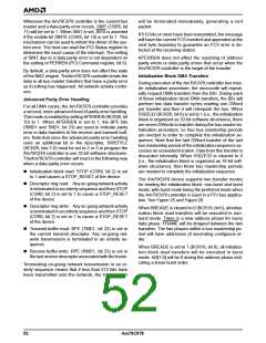
Figure 24 shows a transaction that has a parity error in
the data phase. TheAm79C978 controller asserts
PERR on clock 8, two clock cycles after data is valid.
The data on clock 5 is not checked for parity, because
on a read access, PAR is only required to be valid one
clock after the target has asserted TRDY.
TheAm79C978 controller then drives PERR high for
one clock cycle, since PERR is a sustained tri-state
signal.
Figure 22 assumes that the PCI Latency Timer has
counted down to 0 on clock 7.
During every data phase of a DMA write operation, the
Am79C978 controller checks the PERR input to see if
the target reports a parity error. When it sees the PERR
input asserted, the Am79C978 controller sets PERR
(PCI Status register, bit 15) to 1. When PERREN (PCI
Command register, bit 6) is set to 1, the Am79C978
controller also sets DATAPERR (PCI Status register, bit
8) to 1.
Master Abort
TheAm79C978 controller will terminate its cycle with a
Master Abort sequence if DEVSEL is not asserted
within 4 clocks after FRAME is asserted. Master Abort
is treated as a fatal error by the Am79C978 controller.
Am79C978
49

 AMD [ AMD ]