AMD
P R E L I M I N A R Y
register of TCR4. ADIN2 becomes active after ADIN1 by
the amount of delay specified in the RSSI Sample Start
time of TCR24. ADIN2 remains active for the time pro-
grammed in the A2DT register (TCR25). The converter
output should be connected to the SAR pins, which act
as inputs in this mode.
Baud Determination Logic
The TAI contains Baud Determination logic that sam-
ples the incoming bit stream to determine the data rate.
The result of the Baud Determination is used in making
decisions regarding Clear Channel Assessment and in
selecting an antenna. The Baud Determination logic
functions as follows:
External D/A mode allows the user to connect an exter-
nal D/A converter to the Am79C930 device. The SAR
pins function as outputs and values written to the SAR
register (TIR27) will be driven onto these pins for con-
version by the external D/A device.
Baud Determination testing is performed on a periodic
basis, where the period is determined by the Antenna
Diversity time of TCR4. Baud Determination is intended
to be alternately performed on up to two separate anten-
nas. The antenna diversity decision logic is coupled to
the Baud Determination logic in such a manner that
each successive set of Baud Determination tests is per-
formed on alternating antenna selections. Baud Deter-
mination continues for CCA when an antenna is chosen,
but baud detect results will not affect antenna selection
once an antenna has been locked. Baud detect tests
continue with the periodicity of the dwell timer. Antenna
diversity switching ceases when a satisfactory antenna
has been found. See the section on Automatic Antenna
Diversity logic for antenna selection criteria and testing.
Antenna selection testing resumes following the asser-
tion of either the RXRES bit (RX RESET) of TIR16 or the
RXS bit (RX Start) of TIR16. This action causes the
dwell timer to reset to the value found in TCR4 [5:0] and
then to resume.
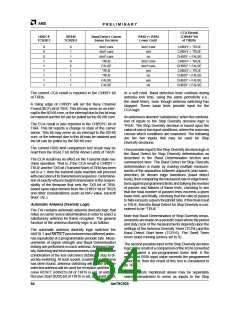
The following table indicates the programming required
in order to effect each mode of the A/D section of the
Am79C930 device:
ADDA
ENEXT
ENSAR
UXA2DST
A/D
TIR26[2] TCR25[6] TCR25[5] TCR25[7]
mode
0
0
0
0
0
0
1
1
0
0
0
0
1
1
X
X
0
0
1
1
0
1
0
1
0
1
internal_A
reserved
internal_B
internal_C
external
0
1
X
X
X
X
reserved
reserved
D/A mode
Because antenna switching can cause transient noise
to appear at the RXD input of the Am79C930 device, the
start of Baud Determination testing is delayed for a pe-
riod of time immediately following the antenna switching
process. In order to accommodate different transceiver/
antenna settling times, the amount of test start delay is
programmable through the Baud Detect Start Timer of
TCR16. Therefore, the duty cycle of the Baud Determi-
nation test period (i.e., the portion of the period during
which Baud test measurements are performed) is equal
totheAntennaDiversitytimeofTCR4minusthevalueof
the Baud Detect Start time of TCR16, minus an addi-
tional three CLKIN periods (6 CLKIN periods if
CLKGT20=1). The three CLKIN periods are used for fi-
nal calculations of Baud Determination, Clear Channel
Assessment, andAntennaselectiononceasetofmeas-
urements has been taken and before a new cycle is al-
lowed to begin.
Physical Header Accommodation
The Am79C930 device can accommodate physical
header information by delaying the start of CRC8 and
CRC32 calculations on outgoing and incoming frames,
until a specified number of bytes beyond the Start of
Frame Detection has become asserted. The length of
the physical header may be anywhere from 0 to 15 bytes
as indicated by the value in the PFL bits of TCR3.
DC Bias Control
An optional DC bias control circuit exists within the
Am79C930 device. This circuit may be disabled through
software control. The circuit uses 16-bit block inversion
and bit stuffing to insure a proper DC balance to the out-
going signal on transmit. Receive signals will automati-
cally have the DC Bias Control removed before further
operations inside of the Am79C930 device. Bit stuffing
may begin with the first bit transmitted after SFD, or at
the beginning of a programmable number of byte times
following the SFD. Receive frames may be “de-stuffed”
inasimilarmanner. DCBiasControlmaybedisabledfor
transmit through a control bit located in TCR1. DC Bias
Control may be disabled for receive through a control bit
located in TCR3. Bit stuffing start control is located
in TCR2 [7].
The Baud Determination measurement process is con-
ducted as follows:
Two counters track the separation between adjacent
falling edges and adjacent rising edges of incoming
receive data. One counter measures the separation
between adjacent falling edges of incoming receive
data, and the other counter measures the separation
between adjacent rising edges of incoming receive
data. Measurement resolution is equal to the CLKIN pe-
riod with the CLKGT20 bit of MIR9 set to 0, and
52
Am79C930

 AMD [ AMD ]