AMD
TAXI Technical Information Publication #89-Nov ’89
S u b je c t : TAXIc h ip Erro r Ra t e Ex a m p le
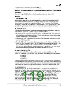
INTRODUCTION
A method was devised to establish a baseline TAXIchip set error rate. A series of tests
were conducted at a transmission rate of 125 MHz at room temperature, and various
power supply voltages. The data collected will be used to determine fiber optic and wire
interconnect BER (Bit Error Rate) tests to be completed at a later date.
METHOD
The test method used the TAXI Transmitters and Receivers to transfer data continu-
ously for at least one thousand hours per pair with different VCC conditions. To imple-
ment this test, five TAXI K2 boards were used. Each board includes a TAXI Transmitter
with a ROM data source, and a Receiver with a ROM data checker to test data integrity
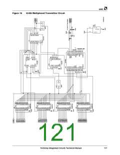
on every byte. They were set up according to the diagrams in Figure 20, and intercon-
nected with AC coupled short coax lines.
In Setup 1, a single power supply with 5 V VCC was attached to TAXI K2 board #1.
Board #1 ran independently with the SEROUT+/– connected to its SERIN+/– with 50 Ω
coaxial cables.
Setup 2 had oscillating voltages (4 V to 6 V) connected to the VCC of TAXI K2 boards #2
and #3. The SEROUT+/– of board #2 were connected to the SERIN+/– of board #3, and
the SEROUT+/– of board #3 connected to the SERIN+/– of board #2, with 50 Ω coaxial
cables, forming two test setups with continually varying power supply voltages.
Setup 3 also uses two power supplies with one set at 4 V and the other at 6 V. These
two power supplies were connected to TAXI K2 boards #4 and #5. The SEROUT+/- and
SERIN+/- were connected in the same configuration as boards #2 and #3 in setup 2 with
50 Ω coaxial cables.
The power supply voltages used (4 and 6 V) are outside the data sheet specification for
the TAXIchip set. This test was intended to stress the parts and to simulate extreme
temperature and operating conditions.
These five boards were checked regularly, and the error counts were recorded. To verify
that these boards were still running correctly, they were made to fail intentionally and
then reset.
RES ULT
The tests were completed after each board ran more than 1,000 hours. The table below
summarizes the results.
Board#
Hours Errors Notes
1
2
3
4
5
1,606
1,623
1,082
1,607
1,082
0
8*
0
2*
0
Errors occurred between 438–558 hours
Errors occurred between 438–558 hours
.
* One error can cause multiple error counts. These were assumed to be one error event.
122
TAXIchip Integrated Circuits Technical Manual

 AMD [ AMD ]