AMD
TAXI Technical Information Publication #89-14
S u b je c t : 3 2 -Bit Mu lt ip le x e d Ca s c a d e w it h t h e TAXIc h ip Tra n s m it t e r
Qu e s t io n :
How can a single TAXIchip Transmitter be used to send n-byte data words?
An s w e r:
I. INTRODUCTION
Many systems have DATA/CMD paths wider than the twelve lines available per TAXI
Transmitter. AMD TAXI applications has designed a circuit which economically multi-
plexes data words longer than eight bits using one TAXI Transmitter. The following
discussion is specifically for an Am7968 Transmitter with a 32-bit data word, but is also
applicable to systems with shorter or longer data words (with or without commands).
II. ADVANTAGES
There are several advantages to using the multiplexed data scheme utilizing one TAXI
Transmitter as opposed to a system using several Transmitters:
1) To implement the mux circuit for 32 bits requires one Am7968 TAXI Transmitter and
three relatively small integrated circuits. A 32-bit wide data path without multiplexing
requires four Am7968 TAXI Transmitters.
2) Four Am7968 TAXI Transmitters require more board real estate than three SSI parts
and one TAXI Transmitter.
3) Four Am7968 TAXI Transmitters will dissipate about 3.5 W, while one Am7968 and
three SSI chips dissipate only 1.25 W. The power saving is even more dramatic if op-
tical data links are being used. A design using four TAXI Transmitters and four
Am79h1000T optical data links would dissipate over 5 W of power. The same 32-bit
wide system using the multiplexing circuit would dissipate only 2.6 W!
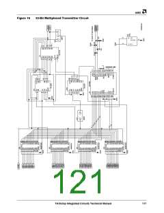
III. IMP LEMENTATION
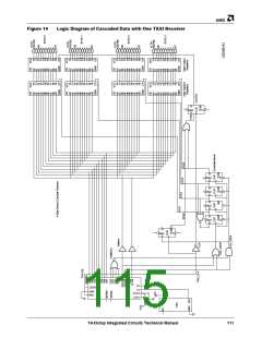
Implementation of the 32-bit multiplexed transmitter circuit is straightforward. (See
Figure 11). In addition to the Am7968 TAXI Transmitter, the following parts are required:
(1) 74LS00
(1) 74LS20
(1) 74LS174
A group of buffers with tri-state outputs (four Am29C821s in this example), would likely
be required in any type of point to point communication application and might already be
available in the host system. Additionally, a number of termination resistors are required.
The number and values are dependent upon the type of coupling and the media used.
IV. OP ERATION
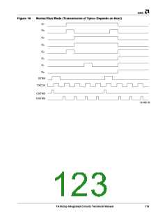
Referring to Figure 15, the data to be transmitted is assumed to be simultaneously
loaded into the buffers when a strobe pulse is input to the system. The controller for the
mux is the 74LS174, which is wired as a shift register. As a 0 (which occurs on strobe) is
shifted through the register, each buffer is enabled in turn. The NAND gate (U1) at the
input of D1, ensures that only a single 0 is possible while the registers are being
selected. The TAXI CLK signal, which is used to clock the 74LS174, is inverted to
provide set-up time to ensure that no false strobes reach the TAXI Transmitter. The
other four-input NAND gate (U2) enables the two-input NAND gate (U3), so that the
Transmitter will be strobed while there is data available in the buffers.
TAXIchip Integrated Circuits Technical Manual
115

 AMD [ AMD ]