S2042/S2048
HIGH PERFORMANCE SERIAL INTERFACE CIRCUITS
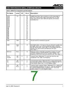
Table 6. S2048 Pin Assignment and Descriptions (Continued)
Pin Name Level I/O
Pin # Description
RX
RY
Diff.
PECL
I
9
10
Receive Serial Input. (Externally capacitively coupled.) The
received serial data inputs. RX is the positive input, and RY is
the negative input.
SYNCEN
TTL
I
3
Sync Enable. Active High. When active, enables sync detection.
When inactive, data is treated as unframed data. Holding this
input at mid-level for more than seven REFCLK cycles puts the
device in PLL Bypass (Test) mode.
REFSEL
TTL
I
I
30
20
Reference Select. (Multilevel.) Input used to select the reference
clock frequency. (See Table 3.)
RATESEL
Static
Multi-
Level
TTL
Rate Select. Multilevel input used to select the operating speed
of the receiver. (See Table 3.)
LOCKREFN
TTL
I
50
Lock to Reference Clock. Active Low. When active, forces the
PLL to lock to the REFCLK input and ignore the serial data
inputs. When inactive, PLL locks to serial data (normal
operation).
ECLVCC
TTLGND
TTLVCC
+3.3 V
GND
–
–
–
13, 27,
39
Core Power Supply
16, 33,
41, 46
TTL Ground
+3.3 V/
+5 V
19, 23,
36, 44
TTL/LVTTL Power Supply.
AVCC
+3.3 V
GND
–
–
–
7
Analog Power Supply
Analog Ground
AVEE
5, 6
ECLVEE
GND
1, 26, 47 Core Ground
April 10, 2000 / Revision B
10

 AMCC [ APPLIED MICRO CIRCUITS CORPORATION ]