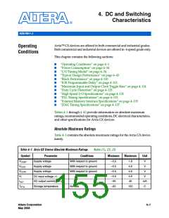
Operating Conditions
Table 4–1. Arria GX Device Absolute Maximum Ratings
Notes (1), (2), (3)
Minimum
Symbol
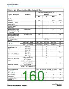
Parameter
Conditions
Maximum
Unit
TJ
Junction temperature
BGA packages under bias
–55
125
C
Notes to Table 4–1:
(1) See the operating requirements for Altera® devices in the Arria GX Device Family Data Sheet in volume 1 of the
Arria GX Device Handbook for more information.
(2) Conditions beyond those listed in Table 4–1 may cause permanent damage to a device. Additionally, device
operation at the absolute maximum ratings for extended periods of time may have adverse affects on the device.
(3) Supply voltage specifications apply to voltage readings taken at the device pins, not at the power supply.
(4) During transitions, the inputs may overshoot to the voltage shown in Table 4–2 based upon the input duty cycle.
The DC case is equivalent to 100% duty cycle. During transitions, the inputs may undershoot to –2.0 V for input
currents less than 100 mA and periods shorter than 20 ns.
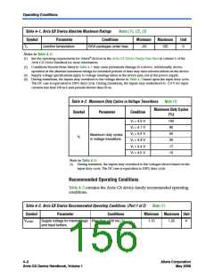
Table 4–2. Maximum Duty Cycles in Voltage Transitions
Note (1)
Maximum Duty Cycles
(%)
Symbol
Parameter
Condition
VI = 4.0 V
VI = 4.1 V
VI = 4.2 V
VI = 4.3 V
VI = 4.4 V
VI = 4.5 V
100
90
50
30
17
10
Maximum duty cycles
in voltage transitions
VI
Note to Table 4–2:
(1) During transition, the inputs may overshoot to the voltages shown based on the
input duty cycle. The DC case is equivalent to 100% duty cycle.
Recommended Operating Conditions
Table 4–3 contains the Arria GX device family recommended operating
conditions.
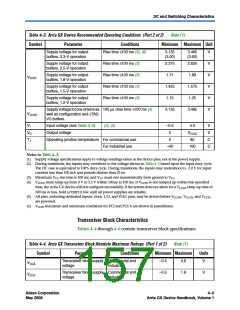
Table 4–3. Arria GX Device Recommended Operating Conditions (Part 1 of 2)
Note (1)
Symbol
Parameter
Conditions
Minimum Maximum Unit
VCCINT
Supply voltage for internal logic Rise time ≤100 ms (3)
1.15
1.25
V
and input buffers
4–2
Altera Corporation
May 2008
Arria GX Device Handbook, Volume 1

 ALTERA [ ALTERA CORPORATION ]