On-Chip Termination
f
For more information on tolerance specifications for on-chip termination
without calibration, refer to the DC & Switching Characteristics chapter in
volume 1 of the Stratix II Device Handbook or the DC & Switching
Characteristics chapter in volume 1 of the Stratix II GX Device Handbook.
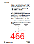
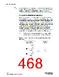
On-Chip Series Termination with Calibration
Stratix II and Stratix II GX devices support on-chip series termination
with calibration in column I/Os in top and bottom banks. Every column
I/O buffer consists of a group of transistors in parallel. Each transistor can
be individually enabled or disabled. The on-chip series termination
calibration circuit compares the total impedance of the transistor group to
the external 25- or 50- resistors connected to the RUPand RDNpins, and
dynamically enables or disables the transistors until they match (as
shown in Figure 4–24). The RS shown in Figure 4–24 is the intrinsic
impedance of transistors. Calibration happens at the end of device
configuration. Once the calibration circuit finds the correct impedance, it
powers down and stops changing the characteristics of the drivers.
1
On-chip series termination with calibration is supported on
output pins or on the output function of bidirectional pins.
Figure 4–24. Stratix II and Stratix II GX On-Chip Series Termination with
Calibration
Stratix II Driver
Series Impedance
Receiving
Device
V
CCIO
R
S
S
Z
O
R
GND
4–30
Altera Corporation
January 2008
Stratix II Device Handbook, Volume 2

 ALTERA [ ALTERA CORPORATION ]