Automotive Grade, Fully Integrated, Hall Effect-Based Linear Current Sensor
with 2.1 kVRMS Voltage Isolation and a Low-Resistance Current Conductor
ACS714
Definitions of Dynamic Response Characteristics
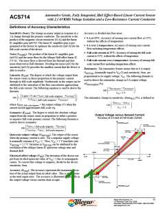
Power-On Time (tPO). When the supply is ramped to its operat-
ing voltage, the device requires a finite time to power its internal
components before responding to an input magnetic field.
Power-On Time, tPO , is defined as the time it takes for the output
voltage to settle within ±10% of its steady state value under an
applied magnetic field, after the power supply has reached its
minimum specified operating voltage, VCC(min), as shown in the
chart at right.
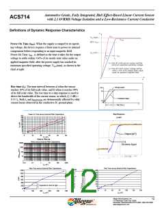
Rise time (tr). The time interval between a) when the sensor
reaches 10% of its full scale value, and b) when it reaches 90%
of its full scale value. The rise time to a step response is used to
derive the bandwidth of the current sensor, in which ƒ(–3 dB) =
0.35/tr. Both tr and tRESPONSE are detrimentally affected by eddy
current losses observed in the conductive IC ground plane.
Primary Current
I (%)
90
Transducer Output
10
0
t
Rise Time, t
r
Step Response
TA=25°C
Power on Time versus External Filter Capacitance
200
180
160
140
120
100
80
IP=5 A
IP=0 A
60
40
20
0
Output (mV)
0
10
20
30
40
50
C
F (nF)
Noise vs. Filter Cap
Noise versus External Filter Capacitance
15 A
10000
1000
100
Excitation Signal
10
1
0.01
0.1
1
10
100
1000
CF (nF)
Rise Time versus External Filter Capacitance
Rise Time versus External Filter Capacitance
CF (nF)
tr (μs)
1200
400
350
300
250
200
150
100
50
0
1
4.7
10
22
47
100
220
470
6.6
7.7
17.4
32.1
68.2
88.2
291.3
623.0
1120.0
1000
800
600
400
200
0
Expanded in chart at right
}
0
0
25
50
75
100
125
150
0
100
200
300
400
500
CF (nF)
CF (nF)
Allegro MicroSystems, Inc.
115 Northeast Cutoff, Box 15036
12
Worcester, Massachusetts 01615-0036 (508) 853-5000
www.allegromicro.com

 ALLEGRO [ ALLEGRO MICROSYSTEMS ]