[AK8975/C]
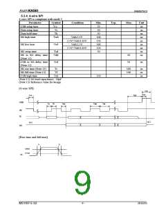
5.3.2. AC Characteristics
Parameter
Symbol
Pin
Condition
Min.
Typ.
Max.
Unit
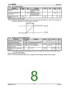
Power supply rise time
(Note 7)
tPUP
VDD
Period of time from
10%Vdd to 90%Vdd
(Note 8)
200
µs
Power-down mode transit
time (Note 7)
VDD
Period of time from
90%Vdd at power-on to
Power-down mode
100
µs
Wait time before mode
setting
Twat
100
s
μ
(Note 7) Reference value for design
(Note 8) Only when VDD meets this condition, POR circuit starts and resets AK8975/C. After reset, all registers are
initialized and AK8975/C transits to Power-down mode.
tPUP
90%Vdd
10%Vdd
5.3.3. Analog Circuit Characteristics
Parameter
Symbol
Condition
Min.
Typ.
Max.
Unit
DBIT
13
bit
Measurement data output bit
TSM
BSE
BRG
Single measurement mode
7.3
0.3
9
ms
Time for measurement
Magnetic sensor sensitivity
Magnetic sensor measurement
range (Note 10)
0.285
-1000
0.315
T/LSB
μ
Tc=25°C (Note 9)
Tc=25°C (Note 9)
±1229
T
μ
Tc=25°C
+1000
LSB
Magnetic sensor initial offset
(Note 11)
(Note 9) Value after sensitivity is adjusted using sensitivity fine adjustment data stored in Fuse ROM. (Refer to
8.3.11 for how to adjust.)
(Note 10) Reference value for design
(Note 11) Value of measurement data register on shipment without applying magnetic field on purpose.
MS1187-E-02
- 8 -
2010/05

 AKM [ ASAHI KASEI MICROSYSTEMS ]