[AK4679]
Addr Register Name
D7
0
D6
MDIF3
R/W
0
D5
MDIF2
R/W
0
D4
MDIF1
R/W
0
D3
INR1
R/W
0
D2
INR0
R/W
0
D1
INL1
R/W
0
D0
INL0
R/W
0
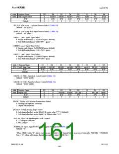
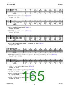
06H
MIC Signal Select
R/W
R
0
Default
INL1-0: MIC-Amp Lch Input Source Select (Table 20)
Default: “00” (LIN1)
INR1-0: MIC-Amp Rch Input Source Select (Table 20)
Default: “00” (RIN1)
MDIF1: Line1 Input Type Select
0: Single-ended input (LIN1/RIN1 pins: default)
1: Full-differential input (IN1+/IN1− pins)
MDIF2: Line2 Input Type Select
0: Single-ended input (LIN2/RIN2 pins: default)
1: Full-differential input (IN2−/IN2+ pins)
MDIF3: Line3 Input Type Select
0: Single-ended input (LIN3/RIN3 pins: default)
1: Full-differential input (IN3+/IN3− pins)
Addr Register Name
D7
MGNR3
R/W
0
D6
MGNR2
R/W
1
D5
D4
D3
D2
D1
D0
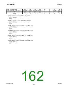
07H
MIC Amp Gain
R/W
MGNR1 MGNR0 MGNL3 MGNL2 MGNL1 MGNL0
R/W
0
R/W
1
R/W
0
R/W
1
R/W
0
R/W
1
Default
MGNL3-0: MIC-Amp Lch Gain Control (Table 21)
Default: “0101” (0dB)
MGNR3-0: MIC-Amp Rch Gain Control (Table 21)
Default: “0101” (0dB)
Addr Register Name
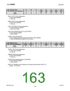
08H Digital MIC
R/W
D7
0
D6
0
D5
PMDMR
R/W
0
D4
D3
D2
0
D1
DCLKP
R/W
0
D0
DMIC
R/W
0
PMDML DCLKE
R
0
R
0
R/W
0
R/W
0
R
0
Default
DMIC: Digital Microphone Connection Select
0: Analog Microphone (default)
1: Digital Microphone
DCLKP: Data Latching Edge Select
0: Lch data is latched on the DMCLK rising edge (“↑”). (default)
1: Lch data is latched on the DMCLK falling edge (“↓”).
DCLKE: DMCLK pin Output Clock Control
0: “L” Output (default)
1: 64fs Output
PMDML/R: Input Signal Select with Digital Microphone (Table 77)
Default: “0”
When DMIC bit is “1”, these registers are enabled. ADC digital block is powered-down by PMDML = PMDMR
bits = “0” when selecting a digital microphone input (DMIC bit = “1”).
MS1402-E-06
2013/02
- 161 -

 AKM [ ASAHI KASEI MICROSYSTEMS ]