[AK4679]
Addr Register Name
D7
FS3
R/W
1
D6
FS2
R/W
1
D5
FS1
R/W
1
D4
FS0
R/W
1
D3
PLL3
R/W
0
D2
PLL2
R/W
1
D1
PLL1
R/W
1
D0
PLL0
R/W
0
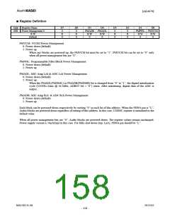
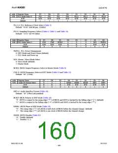
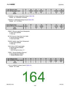
03H
PLL Mode Select 0
R/W
Default
PLL3-0: PLL Reference Clock Select (Table 5)
Default: “0110” (MCKI pin, 12MHz)
FS3-0: Sampling Frequency Select (Table 6, Table 11 and Table 14)
Default: “1111” (fs=44.1kHz)
Addr Register Name
D7
CM1
R/W
0
D6
CM0
R/W
0
D5
BCKO
R/W
0
D4
0
R
0
D3
0
R
0
D2
0
R
0
D1
M/S
R/W
0
D0
PMPLL
R/W
0
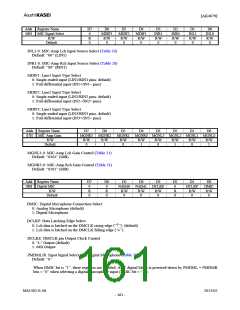
04H
PLL Mode Select 1
R/W
Default
PMPLL: PLL Power Management
0: EXT Mode and Power Down (default)
1: PLL Mode and Power up
M/S: Master / Slave Mode Select
0: Slave Mode (default)
1: Master Mode
BCKO: BICK Output Frequency Select at Master Mode (Table 9)
CM1-0: MCKI Frequency Select at EXT Mode (Table 10 and Table 13)
Default: “00” (256fs)
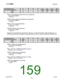
Addr Register Name
05H Audio I/F Format Select
D7
0
R
0
D6
0
R
0
D5
0
R
0
D4
SDOD
R/W
0
D3
MSBS
R/W
0
D2
BCKP
R/W
0
D1
DIF1
R/W
1
D0
DIF0
R/W
0
R/W
Default
DIF1-0: Audio Interface Format (Table 18)
Default: “10” (24bit Left justified)
BCKP: BICK Polarity at DSP Mode (Table 19)
“0”: SDTO is output by the rising edge (“↑”) of BICK and SDTI is latched by the falling edge (“↓”). (default)
“1”: SDTO is output by the falling edge (“↓”) of BICK and SDTI is latched by the rising edge (“↑”).
MSBS: LRCK Phase at DSP Mode (Table 19)
“0”: The rising edge (“↑”) of LRCK is half clock of BICK before the channel change. (default)
“1”: The rising edge (“↑”) of LRCK is one clock of BICK before the channel change.
SDOD: SDTO Disable (Table 83)
“0”: Enable (default)
“1”: Disable (“L”)
MS1402-E-06
2013/02
- 160 -

 AKM [ ASAHI KASEI MICROSYSTEMS ]