[AK4679]
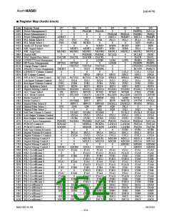
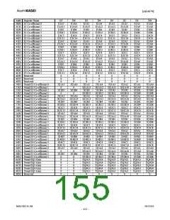
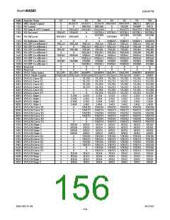
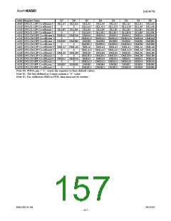
■ Register Definition
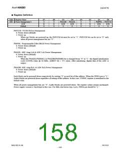
Addr Register Name
D7
0
D6
0
D5
D4
D3
0
D2
0
D1
D0
00H
Power Management 0
PMADR PMADL
PMPFIL PMVCM
R/W
Default
R
0
R
0
R/W
0
R/W
0
R
0
R
0
R/W
0
R/W
0
PMVCM: VCOM Power Management
0: Power down (default)
1: Power up
When any blocks are powered-up, the PMVCM bit must be set to “1”. PMVCM bit can be set to “0” only
when all power management bits are “0”.
PMPFIL: Programmable Filter Block Power Management
0: Power down (default)
1: Power up
PMADL: MIC-Amp Lch & ADC Lch Power Management
0: Power down (default)
1: Power up
When the PMADL(PMDML) or PMADR(PMDMR) bit is changed from “0” to “1”, the digital initialization
cycle (1059/fs=24ms @ 44.1kHz, ADRST bit = “0”) starts. After initializing, digital data of the ADC is
output.
PMADR: MIC-Amp Rch & ADC Rch Power Management
0: Power down (default)
1: Power up
Each block can be powered-down respectively by writing “0” in each bit of this address. When the PDNA pin is “L”,
Audio blocks are powered-down regardless of setting of this address. In this case, CODEC register is initialized to the
default value.
When all power management bits are “0”, Audio blocks are powered-down. The register values remain unchanged.
Power supply current is 50μA(typ) in this case. For fully shut down (typ. 1μA), PDNA pin should be “L”.
MS1402-E-06
2013/02
- 158 -

 AKM [ ASAHI KASEI MICROSYSTEMS ]