[AK4675]
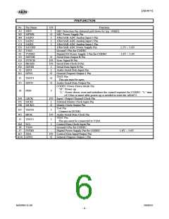
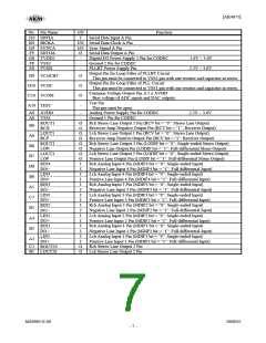
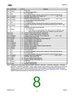
PIN/FUNCTION
No. Pin Name
A1 MDT
I/O
I
O
I
I
I
Function
MIC Detection Pin (Internal pull down by typ. 500kΩ)
MIC Power Supply Pin
B2 MPWR
B4 SAIN3
C5 SAIN2
C4 SAIN1
D3 SAVDD
E2 VSS3
10bit SAR ADC Analog Input 3 Pin
10bit SAR ADC Analog Input 2 Pin
10bit SAR ADC Analog Input 1 Pin
10bit SAR ADC Power Supply Pin
Ground 3 Pin for CODEC
-
-
2.2V ~ 3.6V
1.6V ~ 3.6V
F1 TVDD3
E3 SDTOB
G2 SYNCB
G3 BICKB
H2 SDTIB
J1 SDTI
-
O
Digital I/O Power Supply 3 Pin for CODEC
Serial Data Output B Pin
I/O Sync Signal B Pin
I/O Serial Data Clock B Pin
I
I
O
Serial Data Input B Pin
Audio Serial Data Input Pin
General Purpose Output 1 Pin
TEST Pin
This pin must be open.
Audio Serial Data Output Pin
CODEC Power-Down Mode Pin
“H”: Power-up
K1 GPO1
J2 TEST4
F3 SDTO
O
O
J4 PDN
I
“L”: Power-down, reset and initializes the control registers for CODEC. “L” time
of 150ns or more after power-up is needed to reset the AK4675.
H4 LRCK
H5 MCKI
H6 MCKO
I/O Input / Output Channel Clock Pin
I
O
External Master Clock Input Pin
Master Clock Output Pin
Test Pin
H7 TEST6
K5 BICK
J5 TEST5
I
Connect to DVDD.
I/O Audio Serial Data Clock Pin
TEST Pin
This pin must be connected to VSS4.
I
K6 SCL
J8 VSS4
J7 DVDD
K7 SDA
K10 GPO2
I
-
-
Control Data Clock Input Pin
Ground 4 Pin for CODEC
Digital Power Supply Pin for CODEC
1.6V ~ 3.6V
I/O Control Data Input/Output Pin
General Purpose Output 2 Pin
O
MS0963-E-00
2008/05
- 6 -

 AKM [ ASAHI KASEI MICROSYSTEMS ]