ASAHI KASEI
[AK4115]
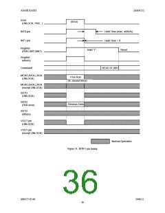
Audio Serial Interface Format
1. LRCK, BICK, SDTO and DAUX
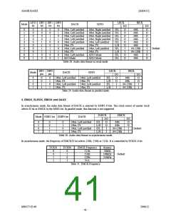
In serial mode, the DIF2-0 bits can select eight serial audio data formats as shown in Table 28. In parallel mode, the DIF0
and DIF1 pins can select four serial audio data format as shown in Table 29. In Mode0-7, the serial data is MSB-first, 2's
complement format. The SDTO is clocked out on the falling edge of BICK and DAUX is latched on the rising edge of
BICK. BICK outputs 64fs clock in Mode 0-5. Mode 6-7 are Slave Modes, and BICK is available up to 128fs at fs=48kHz.
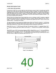
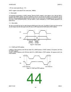
If the data word length is equal or less than 20bit (Mode0-2), the LSBs in the sub-frame are truncated. In Mode 3-7, the
last 4LSBs are auxiliary data (see Figure 34).
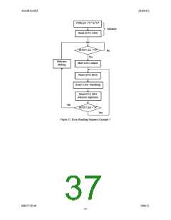
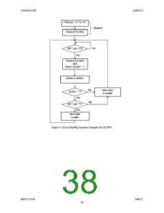
When the Parity Error, Bi-phase Error or Frame Length Error occurs in a sub-frame, the AK4115 continues to output the
last normal sub-frame data from SDTO repeatedly until the error is removed. When the Unlock Error occurs, AK4115
outputs “0” from SDTO. If DAUX is used, the data is transformed and outputted from SDTO. DAUX is used in Clock
Operation Mode 1, 3 and unlock state of Mode 2.
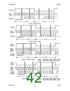
The input data format to DAUX should be left justified except in Mode5 and 7(Table 28). In Mode5 or 7, both the input
data format of DAUX and output data format of SDTO are I2S. Mode 6 and 7 are Slave Modes that corresponds to the
Master Mode of Mode4 and 5. In Slave Mode, LRCK and BICK should be synchronized with MCKO1/2.
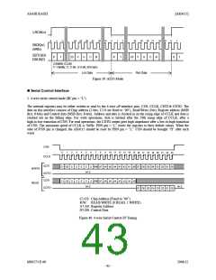
When AES3 bit is set to “1”, SDTO becomes AES3 mode. The serial data is LSB-first, 2’s complement format. The V,
C, U and B bits behind the audio data are added. The B bit goes to “1” when the B-sync in preamble is detected (Figure
39).
When DAUX is sent to SDTO, the data format depends on DIF0 bit. When DIF0 bit is set to “0”, the received MSB-first,
24bit MSB justified is converted to LSB-first, 24bit MSB justified. Then the only audio data is converted and V, U, C
and B bits set to “0”. When DIF0 bit is set to “1”, the AES3 format received from DAUX pin is maintained and is sent to
SDTO pin. Mode 8-9 support only synchronous mode (ASYNC bit = “0”).
sub-frame of IEC958
0
3
4
7
8
11 12
27 28 29 30 31
preamble
Aux.
V U C P
LSB
MSB
LSB
MSB
23
0
AK4115 Audio Data (MSB First)
Figure 34. Bit configuration
MS0573-E-00
2006/12
- 40 -

 AKM [ ASAHI KASEI MICROSYSTEMS ]