ASAHI KASEI
1. Parallel Mode
[AK4115]
In parallel mode, the INT0 pin outputs the ORed signal between UNLCK and PAR. The INT1 pin outputs the ORed
signal between AUTO and AUDION. Once INT0 goes ”H”, it maintains “H” for 1024/fs cycles after all error events are
removed. Table 25 shows the state of each output pins when the INT0/1 pin is “H”.
Event
AUTO
Pin
UNLCK
PAR
AUDION
INT0
“H”
“L”
INT1
SDTO
VOUT
“L”
Output
Output
1
0
0
x
x
x
x
1
0
x
x
x
x
x
x
1
x
0
x
x
x
x
1
0
“L”
Note 40
Previous Data
Output
“H”
“L”
Note 41
Note42
Note 43
Note 40. INT1 pin outputs “L” or “H” in accordance with the ORed signal between AUTO and
AUDION.
Note 41. INT0 pin outputs “L” or “H” in accordance with the ORed signal between UNLCK and
PAR.
Note42. SDTO pin outputs “L”, “Previous Data” or “Normal Data” in accordance with the ORed
signal between UNLCK and PAR.
Note 43. VOUT pin outputs “L” or “Normal operation” in accordance with the ORed signal
between PAR and UNCLK.
Table 25. Error Handling in parallel mode (x: Don’t care)
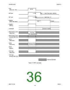
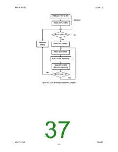
2. Serial Mode
In serial mode, the INT1 and INT0 pins output an ORed signal based on the above nine interrupt events. When masked,
the interrupt event does not affect the operation of the INT1-0 pins (the masks do not affect the registers in 07H and DAT
bit). Once INT0 pin goes to “H”, it remains “H” for 1024/fs (this value can be changed by the EFH1-0 bits) after all
events not masked by mask bits are cleared. INT1 pin immediately goes to “L” when those events are cleared.
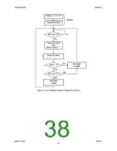
UNLCK, PAR, AUTO, AUDION and VRX bits in Address=07H indicate the interrupt status events above in real time.
Once QINT, CINT and DAT bits go to “1”, it stays “1” until the register is read.
When the AK4115 loses lock, the channel status bit, user bit, Pc and Pd are initialized. In this initial state, INT0 pin
outputs the ORed signal between UNLCK and PAR bits. INT1 pin outputs the ORed signal between AUTO and
AUDION bits.
Event
Pin
UNLCK
PAR
Others
SDTO
“L”
Previous Data
Output
VOUT
“L”
Output
Output
TX
1
0
x
x
1
x
x
x
x
Output
Output
Output
Table 26. Error Handling in serial mode (x: Don’t care)
MS0573-E-00
2006/12
- 35 -

 AKM [ ASAHI KASEI MICROSYSTEMS ]