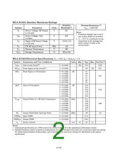
MGA-81563 Absolute Maximum Ratings
Absolute
Thermal Resistance[2]:
=220°C/W
Symbol
Parameter
Units
Maximum[1]
θ
ch-c
Vd
Device Voltage, RF Output
to Ground
V
6.0
Notes:
1. Permanent damage may occur if
any of these limits are exceeded.
2. TC = 25°C (TC is defined to be the
temperature at the package pins
where contact is made to the
circuit board.)
Vgd
Device Voltage, Gate
to Drain
V
V
-6.0
V
in
Range of RF Input Voltage
to Ground
+0.5to-1.0
Pin
Tch
CW RF Input Power
Channel Temperature
Storage Temperature
dBm
°C
+13
165
TSTG
°C
-65to150
MGA-81563 Electrical Specifications, TC = 25°C, ZO = 50 Ω, Vd = 3 V
Symbol Parameters and Test Conditions
Units Min. Typ. Max. Std Dev[2]
Gtest
NFtest
NF50
Gain in test circuit[1]
Noise Figure in test circuit[1]
f=2.0GHz
f=2.0GHz
10.5
12.4
2.8
0.44
0.21
3.8
Noise Figure in 50 Ω system
f=0.5GHz
f=1.0GHz
f=2.0GHz
f=3.0GHz
f=4.0GHz
f=6.0GHz
dB
dB
3.1
3.0
2.7
2.7
2.8
3.5
0.21
0.44
2
|S |
Gain in 50 Ω system
f=0.5GHz
f=1.0GHz
f=2.0GHz
f=3.0GHz
f=4.0GHz
f=6.0GHz
12.5
12.5
12.3
11.8
11.4
10.2
21
P1 dB
Output Power at 1 dB Gain Compression
f=0.5GHz
f=1.0GHz
f=2.0GHz
f=3.0GHz
f=4.0GHz
f=6.0GHz
dBm
15.1
14.8
14.8
14.8
14.8
14.7
0.86
1.0
IP3
Output Third Order Intercept Point
f=2.0GHz
f=2.0GHz
f=2.0GHz
dBm
mA
+27
2.7:1
2.0:1
42
VSWRin Input VSWR
VSWRout Output VSWR
Id
Device Current
31
51
Notes:
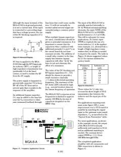
1. Guaranteed specifications are 100% tested in the circuit in Figure 10 in the Applications Information section.
2. Standard deviation number is based on measurement of at least 500 parts from three non-consecutive wafer lots during
the initial characterization of this product, and is intended to be used as an estimate for distribution of the typical
specification.
6-197

 AGILENT [ AGILENT TECHNOLOGIES, LTD. ]