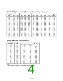
18
16
+5 V
+5 V
+5 V
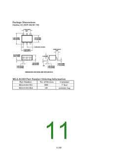
shown in Figure 22 (dimensions
are in inches). This layout pro-
vides ample allowance for pack-
age placement by automated
assembly equipment without
adding parasitics that could
impair the high frequency RF
performanceoftheMGA-81563.
The layout is shown with a
nominal SOT-363 package foot-
print superimposed on the PCB
pads.
Power
Gain
14
12
10
8
Zener
Diode
47 Ω
Silicon
Diodes
6
4
NF
(a)
(b)
(c)
2
0
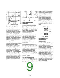
Figure21.BiasingFromHigher
SupplyVoltages.
0
1
2
3
4
5
SUPPLY VOLTAGE (V)
A second method illustrated in
Figure 21b, is to use forward-
biased diodes in series with the
power supply. For example, three
silicon diodes connected in series
will drop a 5-volt supply to
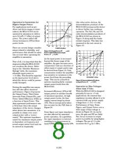
Figure20.Gain,NoiseFigure,and
OutputPowervs.SupplyVoltage.
0.026
Some thermal precautions must
be observed for operation at
higher bias voltages. For reliable
operation, the channel tempera-
ture should be kept within the
165° C indicated in the “Absolute
Maximum Ratings” table. As a
guideline, operating life tests have
established a MTTF in excess of
0.075
approximately 3 volts.
0.035
The use of the series diode
approach has the advantage of
less dependency on current
variation in the amplifiers since
the forward voltage drop of a
diode is somewhat current
independent.
0.016
Figure22.PCBPadLayout
(dimensionsininches).
6
10 hours for channel tempera-
tures up to 150° C.
SMT Assembly
Reliable assembly of surface
mount components is a complex
process that involves many
material, process, and equipment
factors, including: method of
heating (e.g., IR or vapor phase
reflow, wave soldering, etc.)
circuit board material, conductor
thickness and pattern, type of
solder alloy, and the thermal
conductivity and thermal mass of
components. Components with a
low mass, such as the SOT-363
package, will reach solder reflow
temperatures faster than those
with a greater mass.
There are several means of biasing
the MGA-81563 at 3 volts in
systems that use higher power
supply voltages. The simplest
method, shown in Figure 21a, is to
use a series resistor to drop the
device voltage to 3 volts. For
example, a 47 Ω resistor will drop
a 5-volt supply to 3 volts at the
nominal current of 42 mA. Some
variation in performance could be
expected for this method due to
variations in current within the
specified 31 to 51 mA min/max
range.
Reverse breakdown diodes (e.g.,
Zener diodes) could also be used
as in Figure 21c. However, care
should be taken to ensure that the
noise generated by diodes in
either Zener or reverse break-
down is adequately filtered (e.g.,
bypassed to ground) such that the
diode’s noise is not added to the
amplifier’s signal.
SOT-363 PCB Footprint
A recommended PCB pad layout
for the miniature SOT-363 (SC-70)
package used by the MGA-81563 is
6-204

 AGILENT [ AGILENT TECHNOLOGIES, LTD. ]